
Page 65 - Digital Electronics by harish
P. 65
g = A + B + C + C
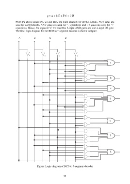
From the above equations, we can draw the logic diagram for all the outputs. NOT gates are
used for complements, AND gates are used for „.‟ operations and OR gates are used for „+‟
operations. Hence, for segment „a‟ we need two 2-input AND gates and one 4-input OR gate.
The final logic diagram for the BCD to 7-segment decoder is shown in figure.
Figure :Logic diagram of BCD to 7-segment decoder
65