Page 314 - YG 2019
P. 314

TECHNICAL                                                                                                             TECHNICAL
                              DATA                                                                                                                  DATA


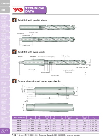
                1    Twist Drill with parallel shank                                                                                   4    Cutting portion

                                                                                                                                                                                                            Detail X
                                                                                                                                                                 Leading edge of land     Margin
                                                                                                                                                   Corner
                                                                                                                                           Flank                                    Ψ
                                                                                                                                                        Margin width b *)  Body clearance diameter  Chisel edge     Heel deburred
                                                                                                                                                                 α
                    Driving tang  Shank diameter                                                                                                                                                X
                          Parallel shank                                                                                                              σ
                                                                                                                                                                                                    d  Drill diameter  Chamferedn
                                                                                                                                                                          Body clearance

                          Shank length                                                                                                            Face     Flute land           Web thickness k  Heel
                                                                                                                                           Cutting lip                                    Flute                     Radiused
                2    Twist Drill with taper shank                                                                                           σ =  Point angle (sigma)

                     Flat tang    Taper shank  Recess(space for inscription)  Cutting portion                                               Ψ =  Chisel edge angle (psi)
                                                                                                                                            * In the context of cutting technology, land width b α  is the body clearance land width which is to be by b fαn , see DIN 6581.
                                                                                                       Drill diameter

                                                                                                      d

                                                                                       Point length                                    5    Angle at the cutting edges
                                 Taper length                           Length of cut section                                               The corner has been adopted as the observed edge point.
                                               Recess length               Flute length
                                                                                                                                                                                                             γ xe
                                                           Overall length                                                                                                                             η
                                                                                                                                                                                                             γ
                3    General dimensions of morse taper shanks                                                                                                                        Corner                           β x


                                                                                                                                                                       Resultant cutting speed angle η
                                                                     A                                                                           Cutting direction                                                            α xe
                         B                                         Diam.                                                                                                                                                α x
                            C                                                          D

                                                                 α    2
                                    F                                                                                                         Direction of cutting motion  Feeds                             Feed direction
                                                        E                    G
                              ≈8°
                                                                                                                                                                          Cutting travel per revolution = d·π

                                                                                                                                      αx    =  Side clearance angle (alpha)
                          H
                                                                                                                                      αxe  =  Effective side clearance angle
                                                                                                                                      βx    =  Side wedge angle (beta)
                                                                                                                                      γx    =  Front rake angle (gamma)

                                                              D
                                                                      E
                                    A
                                             B
                                                                                       G
                 Morse Taper Shank  mm      mm      C(h13)   mm       mm     F(max.)   mm     H(max.)    α  2                         γxe  =  Working front rake angle
                                                                                               mm
                                                     mm
                                                                              mm
                                                                                                                                          =  Resultant cutting speed angle (eta)
                                                                                                                                      η
                     No.1        12.065      9      5.2     12.2      62     13.5     3.5      8.7     1˚ 25´ 43˝
                     No.2        17.780     14      6.3     18.0      75      16       5      13.5     1˚ 25´ 50˝                     Clearance angle α, wedge angle β and rake angle  γ are measured in the tool orthogonal plane. For details, see DIN 6581,
                     No.3        23.825    19.1     7.9     24.1      94      20       5      18.5     1˚ 26´ 16˝                     definitions of metal-cutting technology; geometry at the tool edge.
                     No.4        31.267    25.2     11.9    31.6    117.5     24      6.5     24.5     1˚ 29´ 15˝
                     No.5        44.399    36.5     15.9    44.7    149.5     29      6.5     35.7     1˚ 30´ 26˝
                     No.6        63.348    52.4      19     63.8     210      40       8       51      1˚ 29´ 36˝
               314  •  phone:+1-800-765-8665,  Technical Support : 888-868-5988,  www.yg1usa.com                                                          phone:+1-800-765-8665,  Technical Support : 888-868-5988,  www.yg1usa.com  •  315
   309   310   311   312   313   314   315   316   317   318   319