
Page 317 - YG 2019
P. 317
TECHNICAL TECHNICAL
DATA DATA
6 Web thickness k 8 Angle on Twist Drills
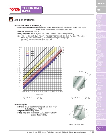
Test values : The web thickness according to Fig. 1 shall not be less than the minimum value k min indicated in Fig. 2. (1) Side rake angle γf (Helix angle)
Test point : At the point of the drill. Recommended test value : Recommended ranges depending on the tool types N,H and W according to
Testing equipment : Slide gauge with measuring points.
DIN 1836 and the diameter of the drill included in Fig. 5.
Test point : At the corner, see Fig. 6.
10mm
8 Testing equipment : According to VDI Guideline 3331 Part 1, Section Margin width b α
6.35 Note : The side rake angle γ is measured in place of the orthogonal rake angle γ O found in the wedge
f
5 measuring plane (see DIN 6581), as this changes along the cutting edge
4 (becoming smaller towards the point of the drill).
3.15
2.5 5° 10° 15 20°
Minimum web thickness k min 1.25 630mm 30°
2
1.6
500
1
35°
40°
0.8
400
45°
0.63
315
0.5
0.4
200
0.315
160
0.25 250
0.2 125
k 1 1.25 1.6 2 2.5 3.15 4 5 6.3 8 10 12.5 16 20 25 31.5 40 50 63 mm 100
100
Drill diameter d 80
Figure 1. Web thickness k Figure 2. Web thickness k min 63
Pitch mm 50
40
7 Margin width bα 31.5 γ f
25
20
16
Test values : The land width as in Fig. 3 shall lie within the limited values indicated in Fig. 4. 12.5
Test point : 5mm behind the corner 10
Testing equipment : Slide gauge 8
6.3
6.3mm 5
5 Upper limited value 4
4 Guide value 1 1.25 1.6 2 2.5 3.15 4 5 6.9 8 10 12.5 16 20 25 31.5 40 50 69 mm 100
3.15 Drill diameter d
2.5 Lower limited value
2 Figure 6. Side rake angle γ Figure 5. Side rake angle γ
1.6 f f
1.25
1
b α
0.8 (2) Point angleσ
0.63
Margin width b α 0.5 Test value : Usual executin for tool types N and H : σ=118°, σ
0.4
for tool type W : σ =130°
Test point : At the cutting, see Fig. 7.
0.315
0.25
0.2 Testing equipment : According to VDI Guideline 3331 Part 1,
0.16 Section Margin width b α
0.125
0.1
0.08
1 1.25 1.6 2 2.5 3.15 4 5 6.3 8 10 12.5 16 20 25 31.5 40 50 63 mm 100
Drill diameter d Figure 7. Point angle σ
Figure 3. Margin width b α Figure 4. Margin width b α
316 • phone:+1-800-765-8665, Technical Support : 888-868-5988, www.yg1usa.com phone:+1-800-765-8665, Technical Support : 888-868-5988, www.yg1usa.com • 317