
Page 93 - 100% Biker (January 2020)
P. 93
SHED HEAD SHEDHEAD IS OUR REGULAR LOOK
AT ALL ASPECTS OF BIKE BUILDING,
DONE BY OUR RESIDENT METAL-
WORKING GENIUS, BLACKJACK
GOING ON A BENDER
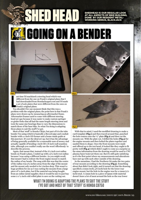
Fig.1 Fig.2
ast time I’d machined a steering head which was
different from the one on Frank’s original plans that I
had downloaded from Hondachopper.com and I’d made
a set of axle plates that were different from the ones on
LFrank’s original plans.
You shouldn’t for one moment think that this was a
problem with the original plans; the point here is that Frank’s
plans were drawn up by measuring an aftermarket frame.
Aftermarket frames used to come with different steering
head set-ups because it was easier to make custom springer
or girder forks that all had the same length steering stem and
took the same size bearings than to vary the dimensions to
match those of the base bike. So what I’m doing is adapting Fig.3
those plans to suit the stuff I’ve got.
Most of that ‘stuff’ is Honda CB750, but part of it is the tube With that in mind, I used the modified drawing to make a
bender I’m using which is basically a Record pipe and conduit card template (Fig.1) and then traced around that, punched
bender with a 1-inch OD former and a home-made guide at the hole centres onto the ¼” plate (Fig.2) and then cut the
this juncture. It’s not the ideal set-up, but it has the advantage mounts out. With the plate cut, I drilled the holes (Fig.3) for
of being generally available for a reasonable sum of money and the engine mounts and then bolted the plates together and
actually capable of bending 1-inch OD 1/8-inch wall seamless sanded them to shape. Once the front mounts were made
tube, although you couldn’t really use the word ‘effortlessly’ to and offered up to the test bend, it looked like they ought to fit
describe the process. pretty well (Fig.4) which didn’t ought to come as a surprise as
Again, that meant that, instead of the 2½-inch root radius the same information from the drawing would be used to CNC
bends on Frank’s plans, I ended up with a 3½-inch root radius plasma/laser/water jet them out. But it’s still quite satisfying
because I was using a different bender. As you might recall, as it’s the first point where my measurements and alterations
that meant I had to redraw the front engine mount to match have met up with each other outside of the drawing.
the radius of my bends. The snag with this was that the centre In the meantime, I had the Northern Git make the two pairs
of the radius was 3¾ inches away from the edge of the mount of rear mounts according to the drawing (Fig.5). Something
and the mount only needed to be 2 inches deep. This wasn’t a about that didn’t look right, and it turned out that the drawing
huge problem for me as I was cutting the mounts from a large specified a 10mm (well, 3/8-inch) hole for the lower rear
piece of ¼-inch plate, but if the material was being bought engine mount, but the hole in the engine was for a 12mm (1/2-
from an online metal supplier, then it would be nice to just buy inch) stud. A 12mm hole in a piece of 25mm wide material
some 2 x ¼-inch cold rolled plate to save on the cutting out. doesn’t leave a lot of meat around the hole so the rear lower
WHAT I’M DOING IS ADAPTING THE PLANS TO SUIT THE STUFF
I’VE GOT AND MOST OF THAT ‘STUFF’ IS HONDA CB750
www.100-biker.com | issue 256 | 100% Biker | 93