
Page 38 - Jetpower (January 2020)
P. 38
034-039 F-22 Raptor:Layout 1 Englisch 09.01.2020 13:49 Uhr Seite 38
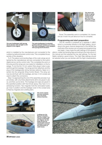
The wheel axle
holder is spring-
loaded and lies
cleanly in the
gear bay when
retracted. A well
solved technique.
Done! The assembly work is completed. An impres-
sive jet. It took me just about an hour to complete.
Programming and start preparation
The RC receiver is powered by a separate 5 UBEC
The nose landing gear with sprung The main landing gear in extended
shock absorber and roll light is well position with the residual cover fitted. which is connected directly to the flight battery. Accor-
adapted to the original. The main landing gear is also equipped ding to the given channel assignment of the MCB-E the
with sprung shock absorbers.
channels of the receiver are occupied and programming
can begin. I have made the path settings of the elevator,
which is installed by the manufacturer and connected to the aileron, rudder and landing flaps according to the instructions in
rudders by ball-and-socket control rods. This completes the as- the manual and first selected the low rate settings. For the test
sembly of the elevators. flights certainly a good choice. The High Rate settings should
To 3: The aileron and landing flaps of the outer wings are at- be selected when you are familiar with the flight characteristics
tached by the manufacturer and are connected to the built-in
digital servos via the control rods. This completes the work on
the wing and the wings are now ready for installation on the fu-
selage. To do this the 10 mm carbon fibre plug-in tube is pas-
sed through the fuselage. The wings are then attached, and the
plug of the fuselage-side wiring harness (ailerons, flaps) is in-
serted into the wing-side Wing Control Board. The wing can
now be slid flush with the fuselage, and two 4 mm screws are
used to attach the connectors.
Step 4 is approaching the end of the assembly process in gi-
ant strides, with only three attachments still to be glued in pla-
ce, and then you're done. The fuselage end caps are glued in
the specified position with five-minute epoxy, they have no lo-
ad-bearing function. Two magnets hold the removable fusela-
ge nose in position and the fuselage cover in the cockpit area
is fixed by magnets and a sliding latch.
The vector control
has been emulated,
but is of course
without function.
Looking over the
Raptor's shoulder
into the cockpit. The
canopy is tinted like
the original. On the
large aircraft the
special gold-coloured
coating is to prevent
the penetration of
radar beams.
38 JETPOWER 1/2020