
Page 37 - Jetpower (January 2020)
P. 37
034-039 F-22 Raptor:Layout 1 Englisch 09.01.2020 13:49 Uhr Seite 37
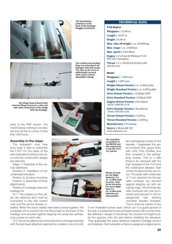
The installation TECHNICAL DATA
positions on the
back of the fuselage:
Plugged and bolted. F-22 Raptor
Wingspan | 13,56 m
Length | 18,87 m
Height | 5,08 m
Max. take off weight | ca. 28.000 kg
Max. range | ca. 3.000 km
Max. speed | 2,25 Mach
Engine | 2 x Pratt & Whitney F119-
PW-100- Turbofans
The rudders and landing Thrust | 2 x 155,69 kN Schub with
flaps are articulated via afterburner
linkages with ball heads.
The clip on the servo is
additionally secured Model
with a piece of heat
shrinkable tubing. Wingspan | 1.500 mm
Length | 1.060 mm
Weight Deluxe-Version | ca. 3.300 g (8s)
Weight Standard-Version | ca. 3.000 g (6s)
Drive Deluxe-Version | 12 Blade EDF
Drive Standard-Version | 9 Blade EDF
Engine Deluxe-Version | Brushless
The Wing Control Board with
inserted Wing Connector, a fast and 4075-1390 KV O/R
safe cable connection of the wings
with the fuselage. Drive Standar-Version | Brushless
3748-1750 KV O/R
Thrust Deluxe-Version | 5.200 g
Thrust Standard-Version | 4.000 g
ment of the PNP version. The Manufacturer | Freewing
model leaves nothing to be desi- Source | MotionRC EU
red and all this at a price of less www.motionrc.eu
than 400 Euros.
The installati-
Assembly in five steps on position of two self-tapping screws at the
The stopwatch runs, how the MCB-E and elevator, I degreased the glu-
long does it take to assemble the connection ed surfaces first, glued them
to the RC recei-
the F-22? On the basis of the ver system. with UHU Plus Endfest and
well illustrated building instructi- then screwed in the self-tap-
on only five construction stages ping screws. This is a safe
are planned: thing to do, because with the
Stage 1: Assembly of the ver- high airspeed of the F-22 and
tical stabilizers the undamped elevator, high
Position 2: Installation of the Plenty of room control surface forces can oc-
undamped elevators for the flight cur. The axles with a diameter
Position 3; Surface mounting batteries. 2 x of 7 mm inserted into the ele-
Position 4; Assembly of three 4s / 5.000 mAH vator surfaces are secured
in series, thus
attachments 8s for the drive. against slipping out with ad-
Position 5 Fuselage nose and For more flight justing rings. The finished ele-
time 2 x
fuselage lid 4s / 6.000 mAh vator surfaces can now be in-
To 1: The rudders on the rud- batteries are serted and secured in the fu-
also possible.
der are attached and must be selage-side ball bearing
connected to the ball control mounted elevator brackets.
rods and the servos already in- This is done by means of two
stalled. When the servo cables have been joined together, the 3 mm threaded screws each, which run in a guide groove of
complete unit is pushed into the fitting seat on the back of the the axle. It is essential to secure these screws with a screw lock.
fuselage and secured against slipping out using two self-tap- But attention: danger of blocking! You should not forget to sli-
ping screws on each side. de the spacers onto the axle before installing the elevators.
To 2: Since the attachment of the aluminium linkage brackets They guarantee the exact distance between fuselage section
with the ball head attached seemed too unsafe to me only with and tailplane. Each elevator surface is assigned a digital servo,
37