
Page 148 - The City and Guilds Textbook: Plumbing Book 1 for the Level 3 Apprenticeship (9189), Level 2 Technical Certificate (8202) and Level 2 Diploma (6035)
P. 148
The City & Guilds Textbook: Plumbing Book 1
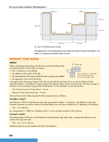
Elbow 1 Elbow 2
500 mm
Bend 3 Bend 4
900 mm
400 mm
Bend 1 Bend 2
920 mm 450 mm
p Figure 2.58 Pipework layout drawing
The pipework is to be fabricated on-site from one piece of tube from elbow 1 to
elbow 2 using measurements taken on-site.
IMPROVE YOUR MATHS
Method X
When calculating and marking out tube for one-piece bending, there Tube stop
are several pieces of information we require:
● the ‘X’ dimension of any fittings X
● the distance to the centre of the clip The 'X' dimension is measured
● the measurements of the space where the tube is going to be installed from the tube stop to the
centre of the socket at 90º
● the pipe gain of any machine bends.
Look again at the drawing in Figure 2.58. We can see that the tube has to fit in an alcove. Elbows will be
required at elbow 1 and elbow 2 simply because the wall has sharp corners at those points. All other changes of
direction can be achieved using machine-made bends. For this example, we will assume that:
The ‘X’ dimension of a 15 mm elbow = 12 mm
Distance to the centre of the clip = 15 mm
Total up the amount of tube required for the one-piece bend, as follows.
From elbow 1 to bend 1
The distance is 900 mm and because pipe clips are present at elbow 1 and bend 1, the distance is the same.
However, because we need to make an end feed elbow joint, we have to deduct the ‘X’ dimension of the elbow:
900 − 12 = 888 mm
So, measurement 1 = 888 mm. Therefore, bend 1 can be marked and bent at this distance.
From bend 1 to bend 2
The distance here is 920 mm, but the bends are fixed between clips either side, so deduct the distance to the
centre of the clip each side:
920 − (15 + 15) = 890 mm
Therefore, bend 2 can be marked and bent at this distance.
➜
136
9781510416482.indb 136 29/03/19 8:54 PM