
Page 161 - APPLIED PROCESS DESIGN FOR CHEMICAL AND PETROCHEMICAL PLANTS, Volume 1, 3rd Edition
P. 161
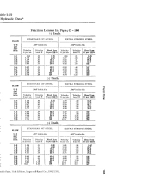
Table 2-22
 Cameron  Hydraulic  Data"


 Friction losses in pipes carrying water   Friction Losses In Pipe; C = 100
 Among  the many empirical  formulae for friction  losses  that have   yg  Inch
 been  proposed  that  of  Williams  and  Hazen  has  been  most  widely
 used.  In a  convenient form  it reads:   STANDARD  WT  STEEL   EXTRA  STRONG  STEEL
 (100)1.ss  q1·s 5   in  which   FLOW            I
 f =  .208:1  -   --- f =  friction  head  111  ft  of  liquid  per
 C   d4·8666   100  ft  of  pipe  (if  desired  in  lb  per   us   .269" inside dia   .215'  inside dia
            iia1
 sq  in.  multiply  f  X  .433  X  sp  gr)   per   ----------·-·--.....--
 d =  inside  dia  of  pipe  in  inches   min   Velocity   Velocity   Head loss   Velocity   Velocity   Head loss
                                                                      ft per 100 ft
 q =  flow  in  gal  per min   ft per sec   bead ft   ft per 100 ft   ft per sec   head ft   ----
 C =  constant  accounting  for  surface   0-1   .565   .00   1-75   .884   .01   6-21
 roughness   0.2      1.13      .02        6-31      1. 77     .05       18.8
 This  formula  gives  accurate  values  only  when  the  kinematic   0-3   1.69   .04   13.4   2.65   .11   3p
                                                                         6  -7
 viscosity  of  the  liquid  is  about  1.1  centistokes  or  :H.5  SSU,  which   0-4   2.26   .08   22.8   3.54   .19   102
                                          34-4
                                                     4.42
                                .12
                      2.83
             0-5
                                                               .30
 is the case with  water at about 60F. But the viscosity of water varies   -
 with  the  temperature  from  1.8 at 32F Lo  .29 centistokes at 2l 2F.   0-6   3.39   .18   48.2   5.32   .44   147
                                                               .61
                                                                        191
                      3.95
                                          64-1
                                                     6.29
                                .24
             0-7
 The tables  are  therefore  subject  to  this  error  which  may  increase   0-8   4.a2   .32   82-0   7.08   . 78   244
 the friction  loss as much  as 20% at 32F and decrease  it as much  as   0-9   5.08   .40   102   7.96   .98
 20%  at  212F.  Note  that  the  tables  may  be  used  for any  liquid   1-0   5.65   .50   124   8.84   1.21   ffl
 having  a  viscosity of the same order as  indicated  above.   ;1Inch
 Values  of  C  for  various  types  of  pipe  are  given  below  together
 with  the  corresponding  multiplier which  should  apply  to  the  tabu-
 lated  values of the  head  loss,  f,  as given  on  pages 29  to 48.   FLOW   STANDARD  WT  STEEL   EXTRA STRONG STEEL
            us              .364• inside dia               .302• inside dia
            �al
            per
            min     Velocity   Velocity   I   Head  loss   Velocity   Velocity   Head loss
 VALUES  OF C       ft per sec   head ft   ft per 100 ft  ft per sec.   head ft   ft  per 100 ft
 Range   Average Commonly   0-4   1. 23   .02   5.22   1. 79   .05       13-0
 value   used   0-6   1. 85     .05       11-1       2.69      .11       27-4
 High=   for   value for   o.8   2.47   .O?   18-8   3.59      .20       46-7
 TYPE  OF  PIPE   hest,   good,   design   1.0   3.08   .15   28-5   4.48   .31   70-6
 smooth,   clean,   purposes   1.2   3. 71   .21   39.9   5.38   .45     98-9
 well laid   new
 pipe        1-i      4.33      .29       53.0       6.27      .61      132
 Low=        1.       4.94      .38       67-9       7.17      .BO      168
 poor or     1.8      5.55      .48       84.4       8.07      1.01     20'}
 corroded    2-0      6.17      .59      103         8.96     l.25      254
 Cement-Asbestos.........................................   160-140  15()  t:�   2.6   7.71   .92   155   11.2   1.95   386
 Fibre.......................................................   150
 Bitumastic-enamel-lined iron or steel centrifugally applied..   160-130   148   140   �Inch
 Cement-lined iron or steel centrifugally applied............   __  150
 __ ,  __  � 1 4�0 __
 Copper, brass, lead, tin or glass pipe and tubing   ::-:-:-;   150-120   140   130   STANDARD  WT  STEEL   i>XTR.A  STRONG  STEEi,
 Wood-stave   ,   ,  ,  .  ,   145--110-   120 · �- l--1,..,l"'O __   FLOW
 Welded and seamless steel.   .°. . . . . . . .  . . . . . . . .  .  .  . . . . . .   150-80-  -i"40   100
 Continuous-interior  riveted  steel  (no  projecting  rivets  or   us   .493" inside dia   .423'  inside dia
 joints   ,  .. , .  . .  . .  . .  . .  . .  . .  .  .  .  . .  . . . .   139   100   gal   -------------
 Wrought-iron  .......•... , .  .  .  . .  . . . . .  . .  .  .  . .  . .  . .  . .  . . . .  . . . . . . .  .  .   150-80   130   100   per
                    Vclocily
                                                                      Head loss
                                       Head loss
                                                   Velocity
 � r  t-iron.d   :...........................................  11540- 5 -8800   113300   mg   mln   ft per sec   Velocily   ft per 100 ft   ft per sec   Velocity   ft per 100 ft
                              head ft
                                                             head ft
 .
 ar.coate  cast-iron
 Girth-riveted steel {projecting rivets in girth seams only)   --- 130- �-   0-8   1.35   .03   4-30   1.83   .05
 Concrete ..... , . .  . .  . .  .  .  .  .  . . .  .  .  .  .  . .  .  .  .  .  .  .  .  .  . .  .  .  .  . .  . .  . .  . .  . .  . . .   152-85   120   100   1.0   1. 68   .04   6-50   2.28   .OB   u·ITT
 Full-riveted  steel  (projecting rivets  in  girth and  horizontal   1-6   2.52   .10   13.8   3.43   .18   L6
 seams)   ,  .. ,  .  .  .  .  .  .  .  .  .  .  .  .  .  .  .  .  .  .  .  .  .  .  .  . . .  .  .  .  .  . .  . . .  .   115   100   2-0   3.36   .IS   23-4   4.57   .32
 Vitrified... . .  .  . . . .  .  .  .  . .  . .  . .  .  .  . .  . .  .  .  . .  . .  .. . .  . .  . . . . .  . . . . .  . .  .  .  .   110   100   2-6   4.21   .28   35.4   5. 71   .51   1d
 Spiral-riveted steel (flow with lap)..........................   110   100
 Spiral-riveted steel (flow against lap).......................   -  -WO-   90   3-0   6.05   .40   :9-6   6.85   . 73   105
                                           6.0
 Corrugated steel   �   ---  ---W --60--   3-5   6.89   .54   84.6   8.00   .99   139
                                                     9.14
                      6.73
             4-0
                                .70
                                                               1.30
 Value of c,   ,   ,  150  1140  1130  1120  1110  1100  I  I  I  I   60   6-0   10.1   1.10   m   11.4   2.0   f8
                                                                         69
                      8.41
 80
 90
 70
                                                                        m
             6.0
 .Multiplicrtocorrecttables.,   47   .G4   .62   .71   .84   1.0  1.22  1.58  1.93  U7   1.58   13. 7   2.9
 *Ry  permission  G.  V.  Shaw and A.  W.  Loomis  C:mn.ermi  Hydraulic Data,  11 th  Edition, Ingersoll-Rand Co.,  1942  [531.