
Page 301 - APPLIED PROCESS DESIGN FOR CHEMICAL AND PETROCHEMICAL PLANTS, Volume 1, 3rd Edition
P. 301
Mechanical Separations 271
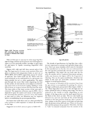
All WILDED CONSTIUCTION. Inlet ond 01,o1let
duct connution1 are weld.cl ond Ron�d.
AUTOMATIC CON-
J 10 LS re;ulote
wo1h-down of moi,-
lure elirriinotor bed
ond opero!lon of
1ludge c.onveyor.
PROTECTIVE COATING
prolec.h all funclionol
C 1teel I componenh.
U------===-- Red'Jce, wear, ero1ion
or corro,ion from wotet
or dull.
STAINLESS sna 1crHn
�:o;t�:!'!�:ton, '---------+-,;· ,111.-!lll'ill!la,'!��
SELF CLEANING detililn prennt1 c.orro1iwe build-
up. There ore no baffles or bladH to wear within
eolleclion area. Entire oreo ii oC"tiwe - no dead
area, for accumulation of dutt,
Overflow-----------
Figure 4-63. Tray-type scrubber
with continuous sludge removal.
Courtesy of National Dust Collec-
tor Corp.
Filters of this type or class may be of the large bag filter Specifications
type for large volumes of low pressure dust laden gases or
vapor, or of the generally smaller cartridge or pack types The details of specifications for bag filter dust collec-
for gas/vapors or liquids containing suspended solid tors are important to a proper and operable design selec-
materials. tion. There are many variables which must be furnished
Figures 4-65, 4-66, and 4-67 show several units of the by the manufacturer so that the user can understand how
bag. The bags may be of cotton, wool, synthetic fiber, and the unit operates mechanically and the unit's dust load-
glass or asbestos with temperature limits on such use as ing capabilities. The larger the air/cloth ratio for the
I80°F, 200°F, 275°F, 650°F respectively, except for unusu- unit, the smaller will be its physical dimensions and gen-
al materials. (See Table 4-12A and B.) These units are erally, cost; however, the higher will be the frequency of
used exclusively on dry solid particles in a gas stream, not cleaning. This can be quite troublesome, therefore low
being suitable for wet or moist applications. The gases values of this ratio are preferable, consistent with the
pass through the woven filter cloth, depositing the dust analysis of overall performance.
on the surface. At intervals the unit is subject to a de-dust- The removal or filtration of the entrained dust from
ing action such as mechanical scraping, shaking or back- the gas stream is accomplished by passing the mixture
flow of clean air or gas to remove the dust from the cloth. through a sufficiently porous fal,ric filter bag(s) (Table 4-
The dust settles to the lower section of the unit and is 14). These bags allow some air to flow through and are
removed. The separation efficiency may be 99%+, but is either cylindrical tubes or oblong tubes/bags. The dust is
dependent upon the system and nature of the particles. retained on the outside or inside (depending on unit
For extremely fine particles a precoat of dry dust similar design) of the bag surface and the small spaces between
to that used in some wet filtrations may be required the fibers of the cloth ( or felt). This dry cake builds up
before re-establishing the process gas-dust flow. and acts as a pre-coat and then as the actual filtering
medium as the dust particles build up. After a period of
For heavy dust loads these units are often preceded by time, unique to the filter system of dust laden air plus bag
a dry cyclone or other separator to reduce the total load type, the pressure drop will build up. (These are low pres-
on the bags. sure and low pressure drop systems.) Therefore, the dust
Suggested air-to-cloth ratios are given in Table 4-13. or "cake" is removed (cleaned) from the outside of the