
Page 14 - 1202 Question Bank Physics Form 5
P. 14
Section C
Answer all questions.
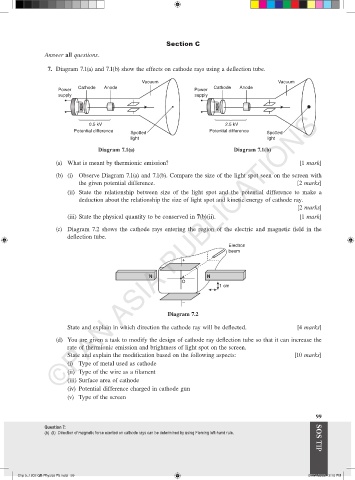
7. Diagram 7.1(a) and 7.1(b) show the effects on cathode rays using a deflection tube.
Vacuum Vacuum
Cathode Anode Cathode Anode
Power Power
supply supply
©PAN ASIA PUBLICATIONS
0.5 kV 2.5 kV
Potential difference Potential difference
Spotted Spotted
light light
Diagram 7.1(a) Diagram 7.1(b)
(a) What is meant by thermionic emission? [1 mark]
(b) (i) Observe Diagram 7.1(a) and 7.1(b). Compare the size of the light spot seen on the screen with
the given potential difference. [2 marks]
(ii) State the relationship between size of the light spot and the potential difference to make a
deduction about the relationship the size of light spot and kinetic energy of cathode ray.
[2 marks]
(iii) State the physical quantity to be conserved in 7(b)(ii). [1 mark]
(c) Diagram 7.2 shows the cathode rays entering the region of the electric and magnetic field in the
deflection tube.
Electron
beam
+
N N
O
1 cm
–
Diagram 7.2
State and explain in which direction the cathode ray will be deflected. [4 marks]
(d) You are given a task to modify the design of cathode ray deflection tube so that it can increase the
rate of thermionic emission and brightness of light spot on the screen.
State and explain the modification based on the following aspects: [10 marks]
(i) Type of metal used as cathode
(ii) Type of the wire as a filament
(iii) Surface area of cathode
(iv) Potential difference charged in cathode gun
(v) Type of the screen
99
Question 7:
(b) (ii) Direction of magnetic force exerted on cathode rays can be determined by using Fleming left-hand rule. SOS TIP
Chp 5_1202 QB Physics F5.indd 99 07/01/2022 2:10 PM