
Page 176 - REPOWER REFERENCE GUIDE (2020)
P. 176
Manifolds, Elbows, and Risers for Wet Joint
Description Nm lb‑in. lb‑ft
Exhaust manifold to cylinder head bolt 43 – 32
2. Using a new gasket, apply sealant to the gasket surface.
Tube Ref No. Description Where Used Part No.
19 Perfect Seal Gasket surface exhaust manifold to elbow and to riser 92-34227Q02
3. Install studs into the manifold for 76 mm (3 in.) risers.
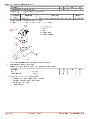
4. Install the exhaust riser and exhaust elbow onto the exhaust manifold.
d a - Gasket surface
b - Gasket
c c - Bolt
d - Exhaust elbow
e - Exhaust manifold
b a
a
e
31547
5. If applicable, install the remote oil assembly with exhaust elbow bolts.
6. Tighten the bolts or nuts to specification.
IMPORTANT: Tighten fasteners evenly using X pattern from corner to corner
Description Nm lb‑in. lb‑ft
Exhaust elbow or riser to exhaust First pass 27 – 20
manifold bolt or nut Final pass 45 – 33
7. For starboard exhaust elbow sterndrive models:
a. Install the drop‑down shift plate bracket, if equipped.
b. Install the shift plate assembly to the elbow.
c. Connect both shift cables.
d. Tighten securely.
Page 7A-6 © 2019 Mercury Marine 90-8M0149179 eng NOVEMBER 2018