
Page 175 - REPOWER REFERENCE GUIDE (2020)
P. 175
Manifolds, Elbows, and Risers for Wet Joint
3. Disconnect the exhaust hoses and the cooling hoses from the exhaust manifold and elbow.
4. On sterndrive models, remove the shift plate.
5. Remove the ECM and the ECM bracket.
6. Remove any other components that are mounted to the manifold, the elbow, or the riser.
7. Remove the elbow and the riser.
8. Remove the exhaust manifold and discard the gaskets.
Cleaning and Inspection
1. Clean the gasket material from all surfaces and wash the parts in solvent.
2. Inspect the water passages for debris. The passages must be clean for efficient cooling.
NOTE: If a more thorough inspection is desired, the pipe plugs may be removed from the exhaust manifold and the
exhaust elbow.
IMPORTANT: If the pipe plugs are removed, coat the threads with sealant before installation.
Tube Ref No. Description Where Used Part No.
Loctite 567 PST Pipe
9 Exhaust manifold and elbow plugs 92-809822
Sealant
3. Inspect for cracks.
4. Inspect all parts carefully. The machined surfaces must be clean and free of all marks and deep scratches or leaks may
result.
5. Inspect for damaged metal caused by saltwater or exhaust gas corrosion in the manifold, elbow, and riser.
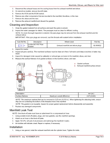
6. Measure the surface flatness of all gasket surfaces on the manifold, elbow, and riser.
b a - Gasket surfaces
b - Exhaust manifold surface shown
a
31546
Description mm (in.)
Surface flatness Maximum overall difference 0.07 (0.003)
NOTE: The maximum material that can be removed is 0.25 mm (0.010 in.). When tightening the attaching bolts, ensure
they are not contacting the bottom of the threaded hole in the manifold.
NOTE: The gasket is not reusable. Inspect for proper gasket replacement before disassembly and assembly.
7. Replace any damaged components.
Manifold Leak Test
NOTE: One block‑off plate must have an attachment for a compressed air hose.
1. Using suitable block‑off plates, plugs, and new gaskets, seal the manifold openings.
2. Attach an air hose to the block‑off plate.
3. Apply 138 kPa (20 psi) of air pressure and submerge the manifold in water.
4. Air bubbles will indicate a leak. Repair or replace, if necessary.
Installation
1. Using a new gasket, install the exhaust manifold onto the cylinder head. Tighten the bolts.
90-8M0149179 eng NOVEMBER 2018 © 2019 Mercury Marine Page 7A-5