
Page 212 - REPOWER REFERENCE GUIDE (2020)
P. 212
Exhaust Systems Installation Requirements—Inboard Applications
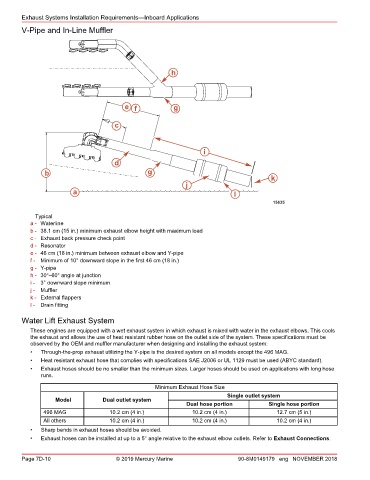
V‑Pipe and In‑Line Muffler
h
e f g
c
i
d
b g
k
j
a l
15635
Typical
a - Waterline
b - 38.1 cm (15 in.) minimum exhaust elbow height with maximum load
c - Exhaust back pressure check point
d - Resonator
e - 46 cm (18 in.) minimum between exhaust elbow and Y‑pipe
f - Minimum of 10° downward slope in the first 46 cm (18 in.)
g - Y‑pipe
h - 30°–60° angle at junction
i - 3° downward slope minimum
j - Muffler
k - External flappers
l - Drain fitting
Water Lift Exhaust System
These engines are equipped with a wet exhaust system in which exhaust is mixed with water in the exhaust elbows. This cools
the exhaust and allows the use of heat resistant rubber hose on the outlet side of the system. These specifications must be
observed by the OEM and muffler manufacturer when designing and installing the exhaust system:
• Through‑the‑prop exhaust utilizing the Y‑pipe is the desired system on all models except the 496 MAG.
• Heat resistant exhaust hose that complies with specifications SAE J2006 or UL 1129 must be used (ABYC standard).
• Exhaust hoses should be no smaller than the minimum sizes. Larger hoses should be used on applications with long hose
runs.
Minimum Exhaust Hose Size
Single outlet system
Model Dual outlet system
Dual hose portion Single hose portion
496 MAG 10.2 cm (4 in.) 10.2 cm (4 in.) 12.7 cm (5 in.)
All others 10.2 cm (4 in.) 10.2 cm (4 in.) 10.2 cm (4 in.)
• Sharp bends in exhaust hoses should be avoided.
• Exhaust hoses can be installed at up to a 5° angle relative to the exhaust elbow outlets. Refer to Exhaust Connections.
Page 7D-10 © 2019 Mercury Marine 90-8M0149179 eng NOVEMBER 2018