
Page 213 - REPOWER REFERENCE GUIDE (2020)
P. 213
Exhaust Systems Installation Requirements—Inboard Applications
• Exhaust elbows must be the prescribed distance above the waterline. Install risers if needed. Refer to Measuring Exhaust
Elbow Height section.
• The exhaust hose attached to the exhaust elbow must have a minimum of 10° downward slope. On longer hose
applications, slope can be reduced to 3° in the portion of the exhaust system that is more than 46 cm (18 in.) away from
the elbow.
NOTE: Mercury MerCruiser's recommendations more stringent than ABYC recommendation of a minimum drop in the
exhaust system of 13 mm (1/2 in.) per foot with an overall drop of not less than 10.2 cm (4 in.) between the exhaust elbow
outlets and the boat outlets.
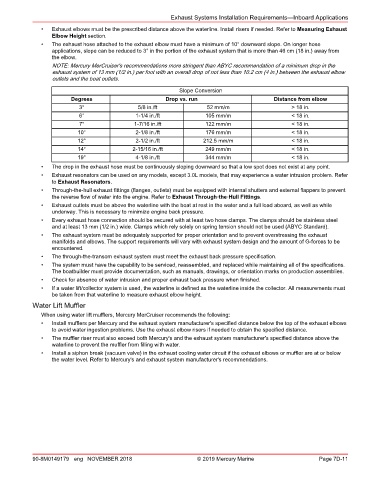
Slope Conversion
Degrees Drop vs. run Distance from elbow
3° 5/8 in./ft 52 mm/m > 18 in.
6° 1‑1/4 in./ft 105 mm/m < 18 in.
7° 1‑7/16 in./ft 122 mm/m < 18 in.
10° 2‑1/8 in./ft 176 mm/m < 18 in.
12° 2‑1/2 in./ft 212.5 mm/m < 18 in.
14° 2‑15/16 in./ft 249 mm/m < 18 in.
19° 4‑1/8 in./ft 344 mm/m < 18 in.
• The drop in the exhaust hose must be continuously sloping downward so that a low spot does not exist at any point.
• Exhaust resonators can be used on any models, except 3.0L models, that may experience a water intrusion problem. Refer
to Exhaust Resonators.
• Through‑the‑hull exhaust fittings (flanges, outlets) must be equipped with internal shutters and external flappers to prevent
the reverse flow of water into the engine. Refer to Exhaust Through‑the‑Hull Fittings.
• Exhaust outlets must be above the waterline with the boat at rest in the water and a full load aboard, as well as while
underway. This is necessary to minimize engine back pressure.
• Every exhaust hose connection should be secured with at least two hose clamps. The clamps should be stainless steel
and at least 13 mm (1/2 in.) wide. Clamps which rely solely on spring tension should not be used (ABYC Standard).
• The exhaust system must be adequately supported for proper orientation and to prevent overstressing the exhaust
manifolds and elbows. The support requirements will vary with exhaust system design and the amount of G‑forces to be
encountered.
• The through‑the‑transom exhaust system must meet the exhaust back pressure specification.
• The system must have the capability to be serviced, reassembled, and replaced while maintaining all of the specifications.
The boatbuilder must provide documentation, such as manuals, drawings, or orientation marks on production assemblies.
• Check for absence of water intrusion and proper exhaust back pressure when finished.
• If a water lift/collector system is used, the waterline is defined as the waterline inside the collector. All measurements must
be taken from that waterline to measure exhaust elbow height.
Water Lift Muffler
When using water lift mufflers, Mercury MerCruiser recommends the following:
• Install mufflers per Mercury and the exhaust system manufacturer's specified distance below the top of the exhaust elbows
to avoid water ingestion problems. Use the exhaust elbow risers if needed to obtain the specified distance.
• The muffler riser must also exceed both Mercury's and the exhaust system manufacturer's specified distance above the
waterline to prevent the muffler from filling with water.
• Install a siphon break (vacuum valve) in the exhaust cooling water circuit if the exhaust elbows or muffler are at or below
the water level. Refer to Mercury's and exhaust system manufacturer's recommendations.
90-8M0149179 eng NOVEMBER 2018 © 2019 Mercury Marine Page 7D-11