
Page 208 - REPOWER REFERENCE GUIDE (2020)
P. 208
Exhaust Systems Installation Requirements—Inboard Applications
Exhaust System Design
Exhaust System Specifications
These engines are equipped with a wet exhaust system in which exhaust is mixed with water in the exhaust elbows. This cools
the exhaust and allows the use of heat resistant rubber hose on the outlet side of the system. These specifications must be
observed by the OEM and muffler manufacturer when designing, manufacturing, and installing the exhaust system:
• Exhaust elbow outlets must be a prescribed distance above the waterline. Install exhaust risers if necessary. Refer to
Measuring Exhaust Elbow Height section.
• The riser height for systems using a water lift muffler is measured to the waterline in the muffler.
Minimum Exhaust Elbow Height
Model Specification
MIE and V‑drive TowSport models 38 cm (15 in.)
TowSport in‑line models 33 cm (13 in.)
• A minimum of 46 cm (18 in.) of exhaust hose must be used between the exhaust elbows and the collector, Y‑pipe, muffler,
or first angular fitting. This portion of the exhaust hose must have a minimum of 10° downward slope. After the first 46 cm
(18 in.), the exhaust system must have a minimum of 3° downward slope. Refer to Measuring Exhaust Elbow Height
section.
• Exhaust hoses can be installed with up to a 5° angle relative to the exhaust elbow outlets. Refer to Exhaust Connections.
• Exhaust back pressure must meet the required specification. Refer to Section 10B ‑ Exhaust Back Pressure Test.
Models Exhaust Back Pressure
1 psi (7 kPa) minimum
All gasoline powered engines 2 psi (14 kPa) optimal
11 psi (76 kPa) maximum
IMPORTANT: Exhaust collectors must drain sufficiently during engine shutdown and idle to provide the drainage necessary for
these operational conditions. Use the following specifications when designing the collector.
Effective Inboard Exhaust System Designs
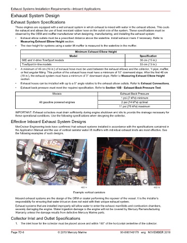
MerCruiser Engineering tests have confirmed that exhaust systems installed in accordance with the specifications contained in
the Application Manual and the use of vertical canister water lift mufflers with individual exhaust inlets are most effective. See
the following examples of such designs.
48514 48516
Example vertical canisters
Inboard exhaust systems are the design of the OEM or dealer performing the repower of the vessel. It is the installer’s
responsibility for ensuring that water intrusion does not exist with their unique exhaust system.
Exhaust systems that are installed improperly will allow water to enter the exhaust manifolds and combustion chambers,
severely damaging the engine. Water ingestion damage to the engine will not be covered by Mercury Remanufacturing
Warranty unless the damage results from defective Mercury Marine parts.
Collector Inlet and Outlet Specifications
1. The inlet hose for the collector must be placed above and within 180° of the horizontal centerline of the collector.
Page 7D-6 © 2019 Mercury Marine 90-8M0149179 eng NOVEMBER 2018