
Page 270 - REPOWER REFERENCE GUIDE (2020)
P. 270
Process Overview
Engine Installation
IMPORTANT: The following items are of particular importance when making the installation. Refer to installation manual for
complete instructions.
Gear Lube Monitor Connection At Gimbal Housing
NOTE: The gear lube monitor hose is now in the parts bag on the engine.
1. Connect the quick release 90 degree fitting of the gear lube monitor hose to the gimbal housing.
a - Hose
b - Quick release 90 degree fitting
c - Gimbal housing fitting
d
a c d - Quickconnect fitting
b
7704
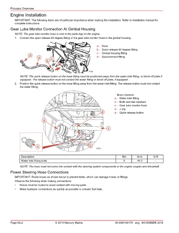
NOTE: The quick release button on the hose fitting must be positioned away from the water inlet fitting, or block‑off plate if
equipped. The release button must not contact the water fitting or block‑off plate, if equipped.
2. Position the quick release button on the hose fitting away from the water inlet fitting. The release button must not contact
the water fitting.
Bravo transom
a - Water inlet fitting
b - Bolts and star washers
c - Gear lube monitor hose
d - J‑clip
d e - Quick release button
a
c
e b
6635
Description Nm lb‑in. lb‑ft
Water inlet fitting bolts 5 44.3 –
NOTE: The hose must not come into contact with the steering system components or the engine coupler and driveshaft.
Power Steering Hose Connections
IMPORTANT: Route hoses as shown below to prevent kinks, which can damage hoses or fittings.
Observe the following when making connections:
• Hoses must be routed to avoid contact with moving parts.
• Make hydraulic connections as quickly as possible to prevent fluid leak.
Page 8A-2 © 2019 Mercury Marine 90-8M0149179 eng NOVEMBER 2018