
Page 275 - REPOWER REFERENCE GUIDE (2020)
P. 275
Critical Procedures
Description Nm lb‑in. lb‑ft
Idler pulley adjustment 9.5–11.5 84.1–101.8 –
Checking
Inspect the drive belt for proper tension and for the following:
• Excessive wear
• Cracks
NOTE: Minor, transverse cracks (across the belt width) may be acceptable. Longitudinal cracks (in the direction of belt
length) that join transverse cracks are NOT acceptable.
• Fraying
• Glazed surfaces
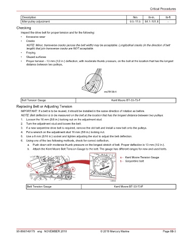
• Proper tension ‑ 13 mm (1/2 in.) deflection, with moderate thumb pressure, on the belt at the location that has the longest
distance between two pulleys.
mc75130-1
Belt Tension Gauge Kent Moore BT‑33‑73‑F
Replacing Belt or Adjusting Tension
IMPORTANT: If a belt is to be reused, it should be installed in the same direction of rotation as before.
NOTE: Belt deflection is to be measured on the belt at the location that has the longest distance between two pulleys.
1. Loosen the 16 mm (5/8 in.) locking nut on the adjustment stud.
2. Turn the adjustment stud and loosen the belt.
3. If a new serpentine drive belt is required, remove the old belt and install a new belt onto the pulleys.
4. Put a wrench on the adjustment stud 16 mm (5/8 in.) locking nut.
5. Use a 8 mm (5/16 in.) socket and tighten adjusting the stud to adjust the belt deflection.
6. Using one of the two following methods, check for correct deflection.
a. Push down with moderate thumb pressure on the longest stretch of belt. Proper deflection is 13 mm (1/2 in.).
b. Attach the Kent Moore Belt Tension Gauge to the belt. The gauge has different ranges for new and used belts.
a - Kent Moore Tension Gauge
b - Serpentine belt
NEWTONE 2.83918
b NEWTONE COLOR GUIDE PATENT
for
a
14980
Belt Tension Gauge Kent Moore BT‑33‑73‑F
90-8M0149179 eng NOVEMBER 2018 © 2019 Mercury Marine Page 8B-3