
Page 243 - Basic Principles of Textile Coloration
P. 243
232 DYEING MACHINERY
venturi passes into a wider storage tube along with the dye solution. The rope
speed is much slower than in the jet section. At the end of the storage tube, the
fabric is drawn off into a narrower tube and returns to the venturi. The dye liquor
is pumped from both ends of the storage tube to a heat exchanger and then to the
jet. Some machines have a long narrow vertical U-tube whereas in others the tube
is horizontal. Several tubes may be situated mounted side by side and share a
common dyebath. They can be isolated for dyeing small lots.
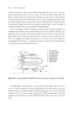
In the so-called soft-flow machines, tension and creasing problems are
minimised. The fabric rope is gently lifted over the short distance between the
dyebath and the transport tube using a circular driven reel. Once in the tube, the
gentle flow of dye solution and gravity carry it around to the exit (Figure 12.7).
The tube supports the fabric and there is no tension. The tube is filled to
overflowing with dye liquor. A typical liquor ratio is about 15:1. Several machines
may share heating and circulation systems.
1 Dye autoclave
2 Circulation system
3 Dye bath pump
4 Heat exchanger
5 Dye bath filter
6 Nozzle/overflow
9 Seam detector
10 Addition tank
Figure 12.7 A typical soft-flow (THENFLOW) jet dyeing machine (courtesy of Then GmbH)
For lightweight or narrow fabrics, dyeing with several parallel ropes in the same
jet is not usually satisfactory because equal lengths are needed and they may give
different degrees of shrinkage. The flyer method of dyeing is used. For this, lengths
of fabric are stitched onto a main carrier rope by their leading edges. They are
slightly shorter than the main rope. Ideally, the fibre of the carrier rope will not be
dyed.