
Page 851 - Elementary_Linear_Algebra_with_Applications_Anton__9_edition
P. 851
11.2 In this section basic laws of electrical circuits are discussed, and it is shown how
these laws can be used to obtain systems of linear equations whose solutions
ELECTRICAL NETWORKS yield the currents flowing in an electrical circuit.
Prerequisites: Linear Systems
The simplest electrical circuits consist of two basic components:
electrical sources denoted by
resistors denoted by
Electrical sources, such as batteries, create currents in an electrical circuit. Resistors, such as lightbulbs, limit the magnitudes of the
currents.
There are three basic quantities associated with electrical circuits: electrical potential (E), resistance (R), and current (I). These
are commonly measured in the following units:
E in volts (V)
R in ohms (Ω)
I in amperes (A)
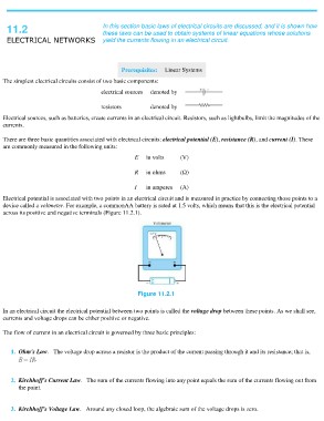
Electrical potential is associated with two points in an electrical circuit and is measured in practice by connecting those points to a
device called a voltmeter. For example, a commonAA battery is rated at 1.5 volts, which means that this is the electrical potential
across its positive and negative terminals (Figure 11.2.1).
Figure 11.2.1
In an electrical circuit the electrical potential between two points is called the voltage drop between these points. As we shall see,
currents and voltage drops can be either positive or negative.
The flow of current in an electrical circuit is governed by three basic principles:
1. Ohm's Law. The voltage drop across a resistor is the product of the current passing through it and its resistance; that is,
.
2. Kirchhoff's Current Law. The sum of the currents flowing into any point equals the sum of the currents flowing out from
the point.
3. Kirchhoff's Voltage Law. Around any closed loop, the algebraic sum of the voltage drops is zero.