
Page 94 - C:\Users\trainee\AppData\Local\Temp\msoEAA3.tmp
P. 94
Document Title
Fundamentals of Stress and Vibration Chapter Title
[A Practical guide for aspiring Designers / Analysts] 2. Engineering Mechanics
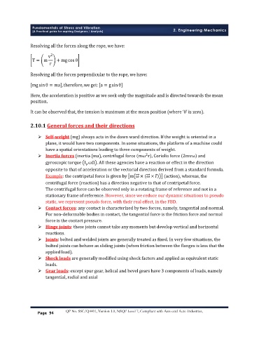
Resolving all the forces along the rope, we have:
v 2
T = m + mgcosθ
r
Resolving all the forces perpendicular to the rope, we have:
mgsinθ = ma ,therefore,we get: a = gsinθ
Here, the acceleration is positive as we seek only the magnitude and is directed towards the mean
position.
It can be observed that, the tension is maximum at the mean position (where ‘θ’ is zero).
2.10.1 General forces and their directions
Ø Self-weight (mg) always acts in the down ward direction. If the weight is oriented in a
plane, it would have two components. In some situations, the platform of a machine could
have a spatial orientations leading to three components of weight.
Ø Inertia forces (inertia (ma), centrifugal force mω r , Coriolis force 2mvω and
2
gyroscopic torque I ωΩ . All these agencies have a reaction or effect in the direction
p
opposite to that of acceleration or the vectorial direction derived from a standard formula.
Example: the centripetal force is given by m ω × ω × r (action), whereas, the
centrifugal force (reaction) has a direction negative to that of centripetal force.
The centrifugal force can be observed only in a rotating frame of reference and not in a
stationary frame of reference. However, since we reduce our dynamic situations to pseudo
static, we represent pseudo force, with their real effect, in the FBD.
Ø Contact forces: any contact is characterized by two forces, namely, tangential and normal.
For non-deformable bodies in contact, the tangential force is the friction force and normal
force is the contact pressure.
Ø Hinge joints: these joints cannot take any moments but develop vertical and horizontal
reactions.
Ø Joints: bolted and welded joints are generally treated as fixed. In very few situations, the
bolted joints can behave as sliding joints (when friction between the flanges is less that the
applied load).
Ø Shock loads are generally modified using shock factors and applied as equivalent static
loads.
Ø Gear loads: except spur gear, helical and bevel gears have 3 components of loads, namely
tangential, radial and axial
Page 94 QP No. SSC/Q4401, Version 1.0, NSQF Level 7, Compliant with Aero and Auto Industries,