
Page 345 - Clinical Application of Mechanical Ventilation
P. 345
Ventilator Waveform Analysis 311
FLOW WAVEFORMS DURING POSITIVE
PRESSURE VENTILATION
Flow, pressure, and volume are the three variables measured and displayed by graphics
in real time. Pressure-volume loops (PVLs) and flow-volume loops (FVLs) are also
pressure-volume loop (PVL):
Graphic display of changes in available. As shown in Figure 11-1, depending on conditions, modes, and manufactur-
pressure and volume during a ers, six distinct flow patterns can be set or can develop during positive-pressure ven-
complete respiratory cycle.
tilation (PPV): the constant flow waveform (CFW); the convex rise (dashed line) in
flow; the descending ramp or concave pattern (dashed line); the ascending ramp, and
flow-volume loop (FVL): sine flow patterns. The CFW can present a convex pattern (dashed line) if the rise time
Graphic display of changes in flow to peak flow rate is slowed for patient comfort during volume-controlled ventilation
and volume during a complete
respiratory cycle. (VCV). What is commonly called the decelerating flow waveform is more appropri-
ately called a descending ramp flow waveform (DRFW) (Chatburn, 2001, 2007).
Depending on the manufacturer, a ventilator may offer a “true” DRFW that descends
constant flow waveform from the initial peak flow level to zero-end-flow as presented in Figure 11-1, or one that
(CFW): Flow-time waveform
where the peak flow occurs at descends to some preset end-flow level above baseline. During pressure-controlled
or near beginning inspiration ventilation (PCV), a DRFW may present an exponential decay or concave pattern
and remains constant until end-
inspiration. (dashed line) depending on lung characteristics and patient effort.
The ascending ramp and sine (also called sinusoidal) waveforms are seldom used
or available for PPV because the initial flow rate is not sufficient to accommodate
volume-controlled ventilation synchronized assisted ventilation for most patients. The fast rise to peak flow offered
(VCV): Mechanical ventilation that
allows the RCP to set the manda- by the CFW and DRFW patterns has proven to be superior in meeting patient flow
tory tidal volume.
demands in clinics and in research.
descending ramp flow
waveform (DRFW): Flow-time 80
waveform where the peak flow Constant Descending Ramp
occurs at or near beginning inspi-
ration and decreases to baseline at V (L/min)
end-inspiration.
·
Inspiration
pressure-controlled ventila-
tion (PCV): A mode of ventilation
in which the peak inspiratory pres-
sure is preset and remains stable in
conditions of changing compliance
V (L/min) 80
and airflow resistance.
· Ascending Ramp Sine
© Cengage Learning 2014
Inspiration
Time (sec)
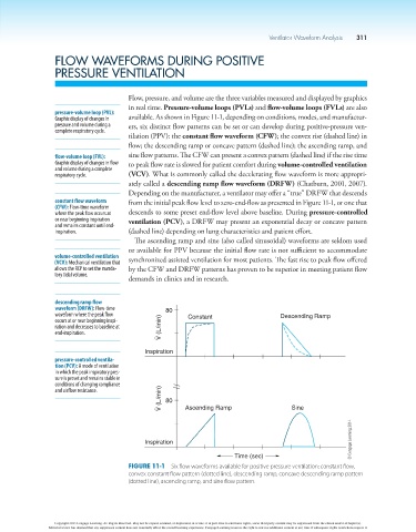
Figure 11-1 Six flow waveforms available for positive pressure ventilation: constant flow,
convex constant flow pattern (dotted line), descending ramp, concave descending ramp pattern
(dotted line), ascending ramp, and sine flow pattern.
Copyright 2013 Cengage Learning. All Rights Reserved. May not be copied, scanned, or duplicated, in whole or in part. Due to electronic rights, some third party content may be suppressed from the eBook and/or eChapter(s).
Editorial review has deemed that any suppressed content does not materially affect the overall learning experience. Cengage Learning reserves the right to remove additional content at any time if subsequent rights restrictions require it.