
Page 88 - Clinical Application of Mechanical Ventilation
P. 88
54 Chapter 3
© Cengage Learning 2014
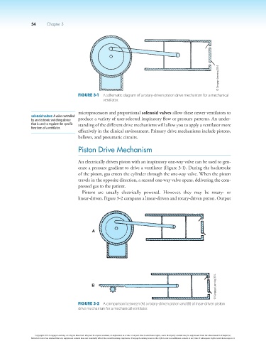
Figure 3-1 A schematic diagram of a rotary-driven piston drive mechanism for a mechanical
ventilator.
microprocessors and proportional solenoid valves allow these newer ventilators to
solenoid valves: A valve controlled
by an electronic switching device produce a variety of user-selected inspiratory flow or pressure patterns. An under-
that is used to regulate the specific standing of the different drive mechanisms will allow you to apply a ventilator more
functions of a ventilator.
effectively in the clinical environment. Primary drive mechanisms include pistons,
bellows, and pneumatic circuits.
Piston Drive Mechanism
An electrically driven piston with an inspiratory one-way valve can be used to gen-
erate a pressure gradient to drive a ventilator (Figure 3-1). During the backstroke
of the piston, gas enters the cylinder through the one-way valve. When the piston
travels in the opposite direction, a second one-way valve opens, delivering the com-
pressed gas to the patient.
Pistons are usually electrically powered. However, they may be rotary- or
linear-driven. Figure 3-2 compares a linear-driven and rotary-driven piston. Output
© Cengage Learning 2014
Figure 3-2 A comparison between (A) a rotary-driven piston and (B) a linear-driven piston
drive mechanism for a mechanical ventilator.
Copyright 2013 Cengage Learning. All Rights Reserved. May not be copied, scanned, or duplicated, in whole or in part. Due to electronic rights, some third party content may be suppressed from the eBook and/or eChapter(s).
Editorial review has deemed that any suppressed content does not materially affect the overall learning experience. Cengage Learning reserves the right to remove additional content at any time if subsequent rights restrictions require it.