
Page 91 - Clinical Application of Mechanical Ventilation
P. 91
Classification of Mechanical Ventilators 57
© Cengage Learning 2014
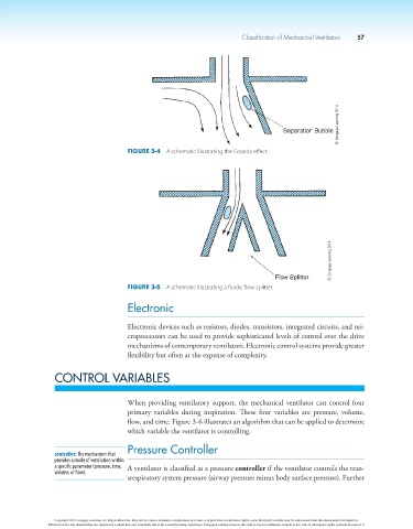
Figure 3-4 A schematic illustrating the Coanda effect.
© Cengage Learning 2014
Figure 3-5 A schematic illustrating a fluidic flow splitter.
Electronic
Electronic devices such as resistors, diodes, transistors, integrated circuits, and mi-
croprocessors can be used to provide sophisticated levels of control over the drive
mechanisms of contemporary ventilators. Electronic control systems provide greater
flexibility but often at the expense of complexity.
CONTROL VARIABLES
When providing ventilatory support, the mechanical ventilator can control four
primary variables during inspiration. These four variables are pressure, volume,
flow, and time. Figure 3-6 illustrates an algorithm that can be applied to determine
which variable the ventilator is controlling.
Pressure Controller
controller: The mechanism that
provides a mode of ventilation within
a specific parameter (pressure, time, A ventilator is classified as a pressure controller if the ventilator controls the tran-
volume, or flow).
srespiratory system pressure (airway pressure minus body surface pressure). Further
Copyright 2013 Cengage Learning. All Rights Reserved. May not be copied, scanned, or duplicated, in whole or in part. Due to electronic rights, some third party content may be suppressed from the eBook and/or eChapter(s).
Editorial review has deemed that any suppressed content does not materially affect the overall learning experience. Cengage Learning reserves the right to remove additional content at any time if subsequent rights restrictions require it.