
Page 25 - Unit2.docx
P. 25
To derive the formulae used in design, we first go through the following procedures:-
2. Decide the location of the N.A of the vertical and the raking piles in
plan position. (see example below).
2. Draw both N.A till they cross each other at point c, this is done in Elevation and
move the forces Q, H& M to point c (see fig.3.5 elevation).
3. Let us assume that the forces Q &M cause lateral and torsional movements
at point c.
4. Point c is where the moment M is zero. Y is the moment arm (see fig. 3.5)
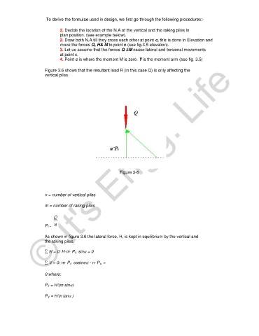
Figure 3.6 shows that the resultant load R (in this case Q) is only affecting the
vertical piles.
© It's Engg. Life
Figure 3-6
n = number of vertical piles
m = number of raking piles
Pv =
As shown in figure 3.6 the lateral force, H, is kept in equilibrium by the vertical and
the raking piles.
∑ H = 0: H-m⋅ P r⋅ sinα = 0
∑ V = 0: m⋅ P r⋅ cosineα - n⋅ P v =
0 where:
P r = H/(m sinα)
P v = H/(n tanα )