
Page 116 - Digital Electronics by harish
P. 116
4.9.2 Expanding memory capacity
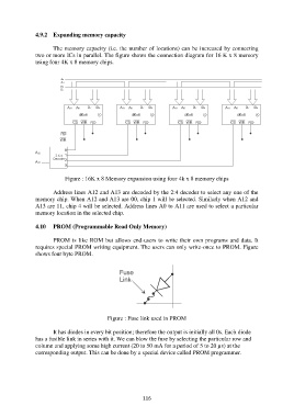
The memory capacity (i.e. the number of locations) can be increased by connecting
two or more ICs in parallel. The figure shows the connection diagram for 16 K x 8 memory
using four 4K x 8 memory chips.
Figure : 16K x 8 Memory expansion using four 4k x 8 memory chips
Address lines A12 and A13 are decoded by the 2:4 decoder to select any one of the
memory chip. When A12 and A13 are 00, chip 1 will be selected. Similarly when A12 and
A13 are 11, chip 4 will be selected. Address lines A0 to A11 are used to select a particular
memory location in the selected chip.
4.10 PROM (Programmable Read Only Memory)
PROM is like ROM but allows end-users to write their own programs and data. It
requires special PROM writing equipment. The users can only write-once to PROM. Figure
shows four byte PROM.
Figure : Fuse link used in PROM
It has diodes in every bit position; therefore the output is initially all 0s. Each diode
has a fusible link in series with it. We can blow the fuse by selecting the particular row and
column and applying some high current (20 to 50 mA for a period of 5 to 20 µs) at the
corresponding output. This can be done by a special device called PROM programmer.
116