
Page 143 - Robot Design Handbook ROBOCON Malaysia 2019
P. 143
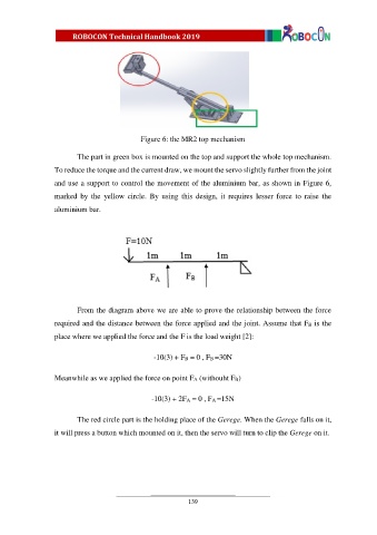
Figure 6: the MR2 top mechanism

                         The part in green box is mounted on the top and support the whole top mechanism.
                  To reduce the torque and the current draw, we mount the servo slightly further from the joint

                  and use a support to control the movement of the aluminium bar, as shown in Figure 6,

                  marked  by  the  yellow  circle.  By  using  this  design,  it  requires  lesser  force  to  raise  the
                  aluminium bar.


                         From the diagram above we are able to prove the relationship between the force

                  required and the distance between the force applied and the joint. Assume that FB is the
                  place where we applied the force and the F is the load weight [2]:


                                                  -10(3) + FB = 0 , FB =30N


                  Meanwhile as we applied the force on point FA (withouht FB)


                                                 -10(3) + 2FA = 0 , FA =15N


                         The red circle part is the holding place of the Gerege. When the Gerege falls on it,
                  it will press a button which mounted on it, then the servo will turn to clip the Gerege on it.


                                                            139