
Page 146 - Robot Design Handbook ROBOCON Malaysia 2019
P. 146
Formula will be used to calculate the radius and the angle or the joystick from the
xy coordinate. Then based on the angle and the radius we will signal the robot to move in
certain direction. In addition, PID controllers are used on the motor to smoothen the
acceleration and deceleration of the motor. This will reduce the sudden increase of speed
and vibration of the robot.
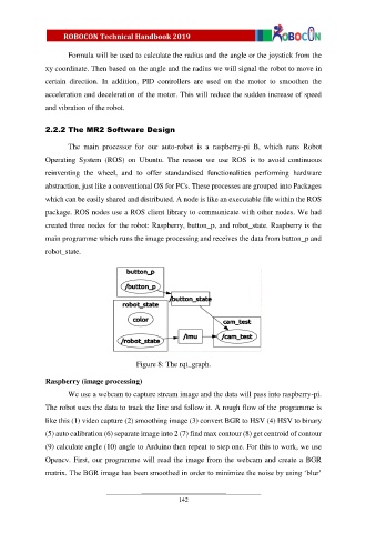
2.2.2 The MR2 Software Design
The main processor for our auto-robot is a raspberry-pi B, which runs Robot
Operating System (ROS) on Ubuntu. The reason we use ROS is to avoid continuous
reinventing the wheel, and to offer standardised functionalities performing hardware
abstraction, just like a conventional OS for PCs. These processes are grouped into Packages
which can be easily shared and distributed. A node is like an executable file within the ROS
package. ROS nodes use a ROS client library to communicate with other nodes. We had
created three nodes for the robot: Raspberry, button_p, and robot_state. Raspberry is the
main programme which runs the image processing and receives the data from button_p and
robot_state.
Figure 8: The rqt_graph.
Raspberry (image processing)
We use a webcam to capture stream image and the data will pass into raspberry-pi.
The robot uses the data to track the line and follow it. A rough flow of the programme is
like this (1) video capture (2) smoothing image (3) convert BGR to HSV (4) HSV to binary
(5) auto calibration (6) separate image into 2 (7) find max contour (8) get centroid of contour
(9) calculate angle (10) angle to Arduino then repeat to step one. For this to work, we use
Opencv. First, our programme will read the image from the webcam and create a BGR
matrix. The BGR image has been smoothed in order to minimize the noise by using ‘blur’
142