
Page 145 - Robot Design Handbook ROBOCON Malaysia 2019
P. 145
is because the voltage that flows through the wire is very high and might burn the wire if
the width of the wire is too small. All the ground pins of the components and the micro-
processor is connected to the rest of the copper of the board which makes it easier during
the design process. 3 pins molex connectors are used to connect the signal pins from the 10
Amp 5 V-30 V DC Motor Driver Cytron. This is to ensure the connection is tight and locked
and does not disconnect easily. The placement of the power supply, the step-down module
and the switch is placed further away from the components. This is to ensure that no short
circuit will occur or will affect the components in any way. Furthermore, the pins headers
which is connected to the components is placed on the outer side of the PCB so that it is
easier it to connect to the modules or component outside of the board respectively. It also
makes it more systematic and organized, thus it will be easier to debug.
2.2 Software Design
2.2.1 The MR1 Software Design
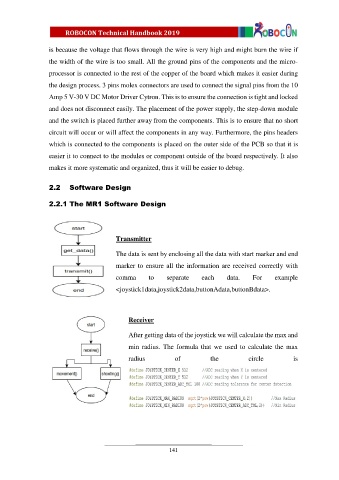
Transmitter
The data is sent by enclosing all the data with start marker and end
marker to ensure all the information are received correctly with
comma to separate each data. For example
<joystick1data,joystick2data,buttonAdata,buttonBdata>.
Receiver
After getting data of the joystick we will calculate the max and
min radius. The formula that we used to calculate the max
radius of the circle is
141