
Page 201 - Robot Design Handbook ROBOCON Malaysia 2019
P. 201
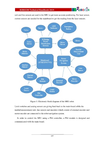
unit and line sensors are used in the MR1 to get more accurate positioning. For laser sensor,
                  current sensors are needed for the mainboard to get the reading from the laser sensors.


                                    Figure 1: Electronic block diagram of the MR1 robot

                  Limit switches and analog sensors are giving feed-back to the main-board while the

                  inertial measurement unit, line sensors and encoders which consist of external encoder and

                  motor encoder are connected to the robot navigation system.

                     In  order  to  control  the  MR1  using  a  PS4  controller,  a  PS4  module  is  designed  and

                  communicated with the main-board.


                                                            197