
Page 202 - Robot Design Handbook ROBOCON Malaysia 2019
P. 202
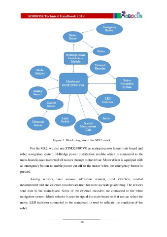
Figure 2: Block diagram of the MR2 robot


                       For the MR2, we also use STM32F407VG as main processor in our main-board and

               robot navigation system. H-Bridge power distribution module which is connected to the
               main-board is used to control all motors through motor driver. Motor driver is equipped with

               an emergency button to enable power cut-off to the motor when the emergency button is
               pressed.


                       Analog  sensors,  laser  sensors,  ultrasonic  sensors,  limit  switches,  inertial
               measurement unit and external encoders are used for more accurate positioning. The sensors

               send data to  the main-board. Some of the external  encoders  are  connected  to  the robot
               navigation system. Mode selector is used to signal the main-board so that we can select the

               mode. LED indicator connected to the mainboard is used to indicate the condition of the

               robot.


                                                          198