
Page 34 - Robot Design Handbook ROBOCON Malaysia 2019
P. 34
2.0 DETAILED DESIGN
In this section, mechanical design, electrical design and software designs for both
robots are provided. Mechanical design was made in Solidworks software. Electronic
circuits and flow-charts for electronic design and software design were made using Visio
software.
2.1 Mechanical Design for the MR1
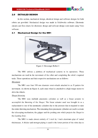
Figure 4: Messenger Robot 1
The MR1 utilizes a plethora of mechanical systems in its operations. These
mechanisms are used in the movement of the robot and completing the robot’s required
tasks. These operations and their respective mechanisms are as follows:
Movement
The MR1 uses four 150 mm diameter omni-wheels attached in an X pattern for
movement. As shown in Figure 4, each omni-wheel is attached to a high torque motor to
drive the wheels.
Shagai throwing
The MR1 uses multiple pneumatic cylinders as well as a linear actuator to
accomplish the throwing of the Shagai. The linear actuator used was brought in as a
replacement to one of the pneumatic cylinders due to the pressure that is required to raise
the entire throwing mechanism. The remaining three pneumatic cylinders are used to actuate
the telescoping mechanism, the gripper and the pushing arm which projects the Shagai to
the Landing Zone.
The MR1 is made almost entirely of 1-inch by 1-inch aluminum pipe of varied
thicknesses. A thicker and stronger piping is used in the lower portion of the robot due to
30