Page 86 - demo
P. 86

BOOK IN SERIES


              Linear Resistances in Parallel:

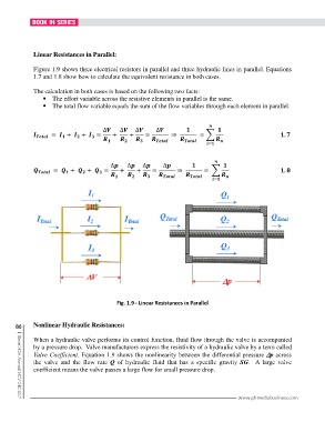
              Figure 1.9 shows three electrical resistors in parallel and three hydraulic lines in parallel. Equations
              1.7 and 1.8 show how to calculate the equivalent resistance in both cases.

              The calculation in both cases is based on the following two facts:
                   The effort variable across the resistive elements in parallel is the same.
                   The total flow variable equals the sum of the flow variables through each element in parallel.


                                                                                
                                        ∆    ∆    ∆      ∆                    
                                                  ⇒                                                         . 
                        
                                    
                              
                                                                 
                                                                               


                                                                                  
                                           ∆    ∆    ∆     ∆                    
                                                         ⇒                                                     . 
                               
                                                                               
                                                                         
                                                                                 


                                             Fig. 1.9 - Linear Resistances in Parallel


       86     Nonlinear Hydraulic Resistances:

              When a hydraulic valve performs its control function, fluid flow through the valve is accompanied
              by a pressure drop.  Valve manufacturers express the resistivity of a hydraulic valve by a term called
              Valve Coefficient. Equation 1.9 shows the nonlinearity between the differential pressure ∆ ∆∆ ∆p across
              the  valve  and  the  flow  rate  Q  of  hydraulic  fluid  that  has  a  specific  gravity  SG.  A large valve
              coefficient means the valve passes a large flow for small pressure drop.


                                                                                           www.ghmediabusiness.com
        |  Global MDA Journal | NOV-DEC 2017
   81   82   83   84   85   86   87   88   89   90   91