
Page 91 - demo
P. 91
BOOK IN SERIES
Yet, these pumps have some drawbacks too, i.e. a design Bearings or bushings are positioned in the two coversopposite
focused on sustaining around 150 – 280 bar, their unsuitability the stator where gear spindles revolve; the transmission shaft
for high flow applications, rather loud noise and a rather poor between the prime mover and the pilot wheel is in the hole
overall efficiency. of the front cover provided with a static seal (see Figure 4.9
Nonetheless, the strong demand for these hydraulic and Figure 4.10). Like in most rotary and reciprocating pumps,
generators prompts manufacturers to carry out research the inlet has a larger bore than the outlet and both of them
and improve their products by employing special materials, are usually positioned one opposite the otheron the stator
accurate heat treatments, minimum coupling tolerance housing.
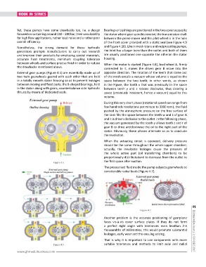
between wheels and surface precise finish in order to reduce When the motor is started (Figure 4.6), lead wheel A, firmly
the drawbacks mentioned above. connected to it, makes the driven gear B move into the
External gear pumps (Figure 4.5) are essentially made up of opposite direction. The rotation of the teeth that come out
two twin gearwheels geared with each other that are held of the mesh entails a vacuum whose volume is equal to the
in a totally smooth stator housing so as to prevent leakages space between the two teeth; in other words, as shown
between moving and fixed parts; the 8-shaped bearings, held in the Figure, the tooth x that was previously in the space
in the stator along with gears, counterbalance side hydraulic between teeth y and z rotates clockwise, thus clearing a
thrusts by means of dedicated seals. space (previously inexistent, hence a vacuum) equal to this
volume.
During this very short phase (rotational speed can range from
few hundreds revolutions per minute to 3000 rpm), the fluid
pushed by the atmospheric pressure on the free surface of
the tank fills the space between the teeth w and k of gear A
and it is driven clockwise to the outlet. In the following phase,
the vacuum generated by the tooth y allows teeth z and r of
gear B to drive anticlockwise the oil to the right part of the
stator. Obviously, these phases alternate so as to conclude
the revolution.
When the actuating circuit is operated, delivery pressure
should be the same throughout the whole upper chamber;
actually, the inevitable leakages cause the pressure of
the whole active part (oil transferring chambers) to be
proportionally distributedand to decrease from the outlet to
the first space after suction.
Figure 4.5
The pressurised fluid inside the pump subjects gearwheels to
considerable radial loads (Figure 4.7).
91
Figure 4.7
Another problem is the accurate positioning of gearplane
faces vis-à-vis cover surface plates. If they do not form
a perfect right angle with tolerances even lessthan 2-3
thousandths of millimetres, this would promote substantial
leakages, early wear and the ensuing seizing. | Global MDA Journal | NOV-DEC 2017
That is why it is important to use components with more
Figure 4.5 suitable tolerances and methods to limit axial and radial
www.ghmediabusiness.com