
Page 89 - demo
P. 89
BOOK IN SERIES
BOOK IN SERIES
HYDRAULICS
in Industrial and Mobile Applications
CHAPTER 4
OIL HYDRAULIC PUMPS
Get your copy of this book :
http://www.assofluid.it/en/publications-requestt
Oil hydraulic pumps are classified first as fixed or
variable displacement pumps.
ven if pressure reaches the maximum limit and the prime
Emover can generate the power needed, flow in fixed
displacement pumps is constant as long as the rotational
speed of the mechanical generator stays the same. Flow rate
changes when the number of revolutions on the transmission
shaft declines: flow diminishes as revolutions per minute
decrease and vice versa; pressure does not change (under Figure 4.1
specific conditions and if the load is constant).
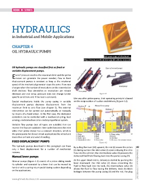
Like any other piston pump, their operating principle is based
Special mechanisms inside the pump casing in variable on the reciprocation of suction and delivery (Figure 4.2).
displacement pumps decrease displacement from the
maximum limit to zero flow (see chapter 5). The external
intervention can be carried out automatically or manually
by means of a hand wheel. In the first case, the dedicated
controllers can be controlled with a mechanical spring, load
sensing, electromechanical or electroproportional system.
Variable flow pumps (not all types are suitable) that can
reverse the flow are available: their outlet becomes the inlet
while their prime mover has a constant direction, which is
the prerequisite for closed circuit applications like wheel and
track drive or hoist and winch handling.
FIXED DISPLACEMENT PUMPS Figure 4.2
The hydraulic pumps described in this paragraph can have By pulling the lever (10) upward, the rod (6) moves the piston 89
only a fixed displacement for a number of mechanical (1) during suction: the inlet valve (2) opens allowing the oil to
reasons. flow into the cylinder; the intermediate valve (3) prevents the
delivered fluid from flowing back into the pump casing (9).
Manual lever pumps
Manual pumps (Figure 4.1) consist of a piston sliding inside At the upper dead centre, delivery is started by pushing the
its cylinder and operated by a lever that can be moved by lever downward: the inlet valve (2) closes preventing the | Global MDA Journal | NOV-DEC 2017
hand or with a spring return pedal during suction depending fluid to flow back into the tank, the intermediate valve (3)
allows the fluid to flow during the delivery. Seals (5) block
on the applications.
leakages between the pump casing (9) and the rod; the plug
www.ghmediabusiness.com