
Page 53 - Jetpower (January 2020)
P. 53
050-051 iGyro SAT:Layout 1 Englisch 09.01.2020 13:55 Uhr Seite 51
Mounting position TECHNICAL DATA and left here, the effective direction of the
The mounting position is set in the gyro is also automatically reversed. A crash
"Gyro Setup" menu. By pressing Size | 20 x 20 x 8 mm on the first flight is almost certain.
"Activate" in the line "Mounting Positi- Weight | 7 g
on" you activate the process and fol- Operating voltage | 4,0 – 9,0 V Programming the gain encoder
low the instructions on the screen. So To do this, simply create the "Gain" functi-
Power Consumption | 20 mA
lift the tail and then deflect it to the on in the function menu, assigning it a rota-
right. The direction of action of the Ampacity | 20 A ry encoder and a free channel / servo. Most
rudders must be ignored in this step. Signal input | FastTrack Bus pilots will certainly be satisfied with these
After that the mounting position is Servo outputs | 5 steps. It was definitely me. But it is possible
programmed. to adjust the individual axes, the general gy-
Servo pulse resolution | 0,5 µs
ro characteristics, the locking behaviour and
Setting the endpoints Gyro control | Heading-, the stick influence on the gyro without any
Normalmode
The endpoints are also taught in problems using the "Fine Tuning" and "Air-
the "Gyro Setup" menu by starting Gyro sensor | MEMS speed Factor" menus.
the process by pressing "Activate" in Price | € 99,–
the "Sticks Endpoints" line. Then sim- Manufacturer | PowerBox Systems First flight
ply follow the instructions on the www.powerbox-systems.com The first flight should always be started with
transmitter display and confirm the the gyro switched off. After trimming, you can
respective required control position slowly turn up the gain control at medium to
by pressing on one of the two arrow keys below the word "Acti- high speed and observe the model. If it starts to oscillate about an
vate". Especially people with a right-left weakness have to pay axis, the sensitivity value must be reduced again. The basic set-
special attention during this step. Because if you swap right ting here is programmed so that when the gain value is increased
in the plus direction, all axes have
only damping mode. If the gain is
increased in the minus direction,
the "Attitude Assist" function is al-
so on the aileron. Attitude Assist
was formerly called Heading-Hold.
If you are now satisfied with your
settings, set the value you have
flown by changing the encoder of
the Gain function in the Function
menu. You swap the encoder for a
switch, and enter the value you ha-
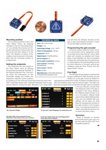
The Telemetry Widget. In the menu "Input Mapping" the channels are set.
ve used in the Servo menu.
Summary
The iGyro SAT can be connected to the In the Gyro Setup menu the mounting position
FastTrack / Data socket of the core receivers. of the iGyro SAT is defined. There is actually no quicker
and simpler way to gyro your mo-
del than with the iGyro SAT from
PowerBox Systems.
JP
51