
Page 507 - The City and Guilds Textbook: Plumbing Book 1 for the Level 3 Apprenticeship (9189), Level 2 Technical Certificate (8202) and Level 2 Diploma (6035)
P. 507
Chapter 7 Central heating systems
Hot water
cylinder
Ground source Two-way
heat pump manifold
Pump Pump
Buried captor or ‘slinky’ 4
2 3 5 6
1 7
Pump Top view
Underfloor heating circuits
The flow and return connections to
the thermostatic mixing valves enter
side by side
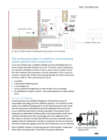
p Figure 7.62 Typical underfloor heating system using a ground source heat pump
The working principles of underfloor central heating
system pipework and components
As we have already seen, underfloor heating works by distributing heat in a
series of pipes laid under the floor of a room. To do this, certain components
are required to distribute the flow of heat to ensure that the system warms
the room. However, the components must be controlled in such a way as to
maintain a steady flow of heat while ensuring that the floor does not become
too hot to walk on. This is achieved by the use of:
l manifolds
l a thermostatic blending valve
l a circulating pump
l various pipework arrangements to suit the floor and its coverings
l the application of system controls – time and temperature to space heating
zones.
The use of manifolds
In technical terms, the manifold is designed to minimise the amount of
uncontrolled heat energy from the underfloor pipework. The manifold is at the
centre of an underfloor heating system. It is the distribution point where water
from the heat source is distributed to all of the individual room circuits and,
as such, should be positioned as centrally as possible in the property. Room
temperature is maintained via thermostatic motorised actuators on the return
manifold, while the correct flow rate through each coil is balanced via the
flow meters on the flow manifold. Both the flow and return manifolds contain
isolation valves for maintenance activities, an automatic air valve to prevent air
locks and a temperature gauge so that the return temperature can be monitored.
Most manifolds contain a circulating pump and a thermostatic mixing valve, p Figure 7.63 Typical underfloor
often called a blending valve. These will be discussed a little later. heating manifold
495
9781510416482.indb 495 29/03/19 9:03 PM