
Page 508 - The City and Guilds Textbook: Plumbing Book 1 for the Level 3 Apprenticeship (9189), Level 2 Technical Certificate (8202) and Level 2 Diploma (6035)
P. 508
The City & Guilds Textbook: Plumbing Book 1
The thermostatic mixing (blending) valve
Thermostatic mixing or blending valves are designed to mix the flow and
return water from the heat source to the required temperature for the
underfloor heating circuits. They are available in many different formats, the
most common being as part of the circulating pump module, as shown in
Figure 7.64. The temperature of the water is variable by the use of an adjustable
thermostatic cartridge inside the valve.
The circulating pump
The circulating pump is situated between the thermostatic mixing valve and the
flow manifold to circulate the blended water through every circuit. Most models
are variable speed.
Underfloor heating pipework arrangements
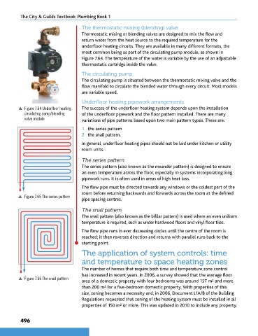
p Figure 7.64 Underfloor heating The success of the underfloor heating system depends upon the installation
circulating pump/blending of the underfloor pipework and the floor pattern installed. There are many
valve module variations of pipe patterns based upon two main pattern types. These are:
1 the series pattern
2 the snail pattern.
In general, underfloor heating pipes should not be laid under kitchen or utility
room units.
The series pattern
The series pattern (also known as the meander pattern) is designed to ensure
an even temperature across the floor, especially in systems incorporating long
pipework runs. It is often used in areas of high heat loss.
The flow pipe must be directed towards any windows or the coldest part of the
room before returning backwards and forwards across the room at the defined
p Figure 7.65 The series pattern
pipe spacing centres.
The snail pattern
The snail pattern (also known as the bifilar pattern) is used where an even uniform
temperature is required, such as under hardwood floors and vinyl floor tiles.
The flow pipe runs in ever decreasing circles until the centre of the room is
reached; it then reverses direction and returns with parallel runs back to the
starting point.
The application of system controls: time
and temperature to space heating zones
The number of homes that require both time and temperature zone control
has increased in recent years. In 2006, a survey showed that the average floor
p Figure 7.66 The snail pattern
area of a domestic property with four bedrooms was around 157 m and more
2
than 200 m for a five-bedroom domestic property. With properties of this
2
size, zoning becomes a necessity and, in 2006, Document L1A/B of the Building
Regulations requested that zoning of the heating system must be installed in all
2
properties of 150 m or more. This was updated in 2010 to include any property.
496
9781510416482.indb 496 29/03/19 9:03 PM