
Page 673 - The City and Guilds Textbook: Plumbing Book 1 for the Level 3 Apprenticeship (9189), Level 2 Technical Certificate (8202) and Level 2 Diploma (6035)
P. 673
Chapter 11 Electrical principles and processes for building services engineering
Polarity can be checked by different methods, including visual inspection and
continuity testing. The main point is to ensure that the line and neutral are not
crossed over in a circuit.
Polarity and continuity testing
This test uses the same low-resistance ohmmeter as the previous tests and it
is again essential to ensure safe isolation has been followed carefully to avoid
the risk of electric shock. Once the meter has been selected, checked and low
ohm range chosen, the leads are zeroed. The main switch on the consumer unit
is off, lamps removed, all fuses removed, circuit breakers and RCBOs are off. A
temporary link is put into the safely isolated board as shown in the diagram.
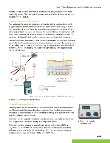
The low-resistance ohmmeter is then connected between the line and cpc in the
switch. To check polarity, the meter is connected next between the line and cpc
in the ceiling rose at the end of the circuit. By turning the switch on and off the
meter will show a low reading followed by a high reading, proving polarity as
the circuit is broken.
Ceiling rose
at end of circuit
Temporary link
Switch
Main switch off
All fuses removed
Circuit breakers off
Test instrument 0.20Ω
Lamps removed
Note: the test may be carried out either at lighting points or switches
p Figure 11.31 Polarity and continuity testing
Insulation resistance
The purpose of the insulation test is to verify that the insulation of conductors
provides adequate insulation, is not damaged and that the live conductors or
protective conductors are not short-circuited or leaking over-current that could
give rise to fire or electric shock.
The meter used is a specific insulation resistance meter (or multifunction meter
that is approved). The meter setting is in megaohms (MΩ). p Figure 11.32 Insulation
resistance meter
The meter must be capable of supplying an output test voltage of 250 V
DC, 500 V DC or 1,000 V DC For standard domestic installations, the meter
will need to go up to 500 V DC and readings that can be expected between
conductors can range from 0.00 MΩ to over 2,000 MΩ.
661
9781510416482.indb 661 29/03/19 9:09 PM