
Page 116 - APPLIED PROCESS DESIGN FOR CHEMICAL AND PETROCHEMICAL PLANTS, Volume 1, 3rd Edition
P. 116
100 Applied Process Design for Chemical and Petrochemical Plants
I SHEET NO.---------
LUDWIG CONSULTING ENGINEERS
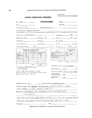
LINE SIZE SHEET
Joi, Ho. ----------
Date _ Charge Ha. _
Line Ha. LP - 51 _ Flow ShHt Drowi.ng Ha. _
Line Description Reactor Discharge
280
Fluid In line Crude Product Temperature -------'--'---- F
0
GPM (Cale.) 23,7 GPM (des.) 25 Pressur"'t ------�3=-5_0_psig
CFM (Cale.) CFM (des.) Sp. Gr.0. 93
L bs./hr. (Cale.) Lbs./hr.(des.) Sp. Vol. -------- cu.ft./11,.
0.91
Recommended V eloclty 6,o fp_s __ Viscosity __________ cp
Straight pipe, fittings, valves Pr� 1 sure. Drop
expon1(on, contraction, etc. Item 1n, ps I
Item Mo. Unit E q. Ft. Tata I E q. Ft. Pipe & Equivole"t c: )
Pipe 254 I 254 Orifice c ) - In
90°Elbow 10 4 40 ,': Motor Valve (��"�rr.1) �l,n
Tee 8 3 24 Mi scel raneous
Gate Va. 4 I 4
Total ':!c;n
Total 32g 1,
Estimated line size H:" (ye r j f j ed)
* Rounded total to 75 feet
** By difference Actual Velocity fp s
Inlet= 350 psig; Outlet= 0 psig Unit Loss per 100 ft. 1. si ss i (see belQ\:l)
Friction Loss= 10 (includes orifice loss)
Balance for Valve= 340 psi Total head loss 869
in feet of liquid
Total pressure
drop in psi 350
Selected pipe ,I�• _ _._ ) 4 · '- ' -------- Material & Weight Schedule 40 steel
Calculatlons: Re = so.6 QPl<y«= 50,6(25) (0.93 x 62.3)/(1.61) (0.91) 50,025
t
�Id= 0.0012; f = 0.021 (Figures 2-3 and 2-11)
l:a.P/100' 0.0216 f/J Q2 / ds = 0.0216(0.021) (62.3) (0.93) (25)2/(1.65)5
J
1.52 psi/100 ft.
Total Pipe System Friction AP =((329) (l.52/100)) + 5,'< = 10 psi for friction; >'<Orifice
Total Loss, Feet Liquid= 350(2.31ft./psi)(l/0.93) = 869 feet of Liquid
Checked by: _ Date: _
Figure 2-28. Line sizing sheet for example problem, Example 2-7.