
Page 117 - APPLIED PROCESS DESIGN FOR CHEMICAL AND PETROCHEMICAL PLANTS, Volume 1, 3rd Edition
P. 117
Fluid Flow 101
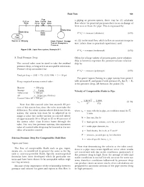
,-u--- Vo Ive Valve Valve a piping or process system, there may be ( 1) adiabatic
Flaw
Orifice
Gate Control Gale
Dow where for practical purposes there is no exchange of
Plate
heal into or from the pipe. This is expressed by:
*Gale
------ Valve Globe P' V/ = constant (adiabatic) (2-73)
Valve
Dip,
Pipe I
Reactor Ill 350 psig Crude Product Storage or, (2) isothermal flow, which is flow at constant tempera-
Tank at Atmospheric ture ( often close to practical experience) and:
Pressure
Figure 2-29. Liquid flow system, Example 2-7.
P' Va= constant (isothermal) (2-74)
9. Total Pressure Drop Often for a large variety of process gases, some relation-
ship in between expresses the pressure-volume relation-
The control valve must be sized to take the residual ship by:
pressure drop, as long as it is an acceptable minimum.
Pressure drop accounted for:
P' Va" = constant (polytropic) (2-75)
Total psi drop= (245 + 75) (1.52/100) + 5 = 10 psi
For gases/vapors flowing in a pipe system from point 1
Drop required across control valve: with pressure P 1 and point 2 with pressure P 2, the P 1 - P 2
is the pressure drop, �P, between the points [3].
Reactor = 350 psig
Storage O psig Velocity of Compressible Fluids in Pipe
Differential = 350 psi
6.P = 10 psi (sys. friction)
Control Valve L'.P = 340 psi
3.06 WV 3.06\,\1 (2- 76)
d ? d2p
Note that this control valve loss exceeds 60 per-
cent of this system loss, since the valve must take the
difference. For- other systems where this is not the sit- where vm = mean velocity in pipe, at conditions stated for V,
uation, the system loss must be so adjusted as to ft/min.
assign a value (see earlier section on control valves)
of approximately 10 to 20 psi or 25 to 60 percent of \V = flow rate, lbs/hr
the system other than friction losses through the V = fluid specific volume, cu ft/lb, at T and P
valve. For very low pressure systems, this minimum
value of control valve drop may be lowered at the sac- d = inside pipe diameter, in.
rifice of sensitive control. p = fluid density, lbs/ cu ft, at T and P
P' = pressure, pounds per sq foot absolute
Friction Pressure Drop For Compressible Fluid Flow
k = ratio of specific heats, cp/c"
Vapors and Gases
Note that determining the velocity at the inlet condi-
The flow of compressible fluids such as gas, vapor, tions to a pipe may create significant error when results
steam, etc., is considered in general the same as for liq- are concerned with the outlet conditions, particularly if
uids or non-compressible fluids. Specific semi-empirical the pressure drop is high. Even the average of inlet and
formulas have been developed which fit particular sys- outlet conditions is not sufficiently accurate for some sys-
tems and have been shown to be acceptable within engi- tems; therefore conditions influenced by pressure drop
neering accuracy. can produce more accurate results when calculations are
Because of the importance of the relationship between prepared for successive sections of the pipe system (long
pressure and volume for gases and vapors as they flow in or high pressure).