
Page 191 - APPLIED PROCESS DESIGN FOR CHEMICAL AND PETROCHEMICAL PLANTS, Volume 1, 3rd Edition
P. 191
Fluid at approximately 60% of discharge
pressure Is circulated through the bear-
ings and over the rotor for cooling and Dry St•tor
lubrication and returns through the hol- Eliminates oH pressure relief valve re-
low shaft to suction pressure.
quired for oH filled stators. Integrity of �Fl•nges
secondary leak containment shell Is 150 and 300 pslg rating (raised face).
Terminal Plate----------------,iJj maintained.------� Seit venting centerline discharge. Com-
O-rtng sealing lor positive secondary patible with ANSI 673.1 dimensions.
lluld containment.
Be•rlng Monitor---------,
The standard bearing monitor solves the
most basic problem common to all seal-
less pumps-detecting normal bearing
wear so that routine maintenance can be
accomplished before serious motor
damage occurs. It responds to bearing
wear in both the axial and radial direc-
tions and is over 98% affective on "'CJ
c:
70,000 operational units. 3
In addition, the monitor is useful in de- "C
s·
tecting corrosion of the stator liner and Impeller (C
rotor sleeve since the contact tip is High efficiency design, open and closed
supplied in the same metallurgy but configurations. 2.
r
one-half the thickness of those compo- .. ci"
nents. (Optional flow Inducers avallabte for min- c:
imum NPSH requirements.) a:
Sh•ft Sleeves ....., (/)
Available in a variety of surface treat-
ments to suit the specific fluid applica-
tions. Replaced when bearings are
changed for like new wear surfaces and Bearings Hollow Sh•ft (B•sic, Thermoat•ts Thrust W•shera
clearances. Available in a variety of materials to suit HB and HX Models Only) Embedded In the hot spot of the wind- Absorb thrust loads during upset condi-
the specific fluid application. Oversized Assures complete self-venting and pre- ings for protection against overheating. tions and provide back·up to hydraulic
for minimum loading. vents vapor collection at the bearings. thrust balancing.
Motor8
In the Sundyne Canned Motor design, stator liner to cool the motor, and lubri- application to assure full winding life.
the entire outside of the motor is en- cate the bearings. Thermostats are embedded In the hot
closed in a secondary leakage contain- Motor windings and Insulation systems spots of windings for shutdown In case
ment shell or can. Primary leakage pro- are specially designed, developed and of overheating.
tection is provided by corrosion resistant applied as an Integral part of the pump Motors are suitable for use In general
liners which are seal welded and 100% so that design life is at least as great as purpose areas and In Class I, Division 2,
leak checked to assure that pumped for conventional air cooled motors. Group C and D areas for a wide range of
fluid does not contact the stator windings Winding temperature Is primarily Influ- pump fluid temperatures. For Class I,
or rotor core. There Is no shaft protrusion enced by pumped fluid temperature and Division 1 Group C and D; U.L. fisted,
to seal and thus no seals to leak. secondarily by use of cooling Jacket. explosion proof motors are available.
Pumped fluid Is circulated Inside the Fluid temperature Is considered In pump
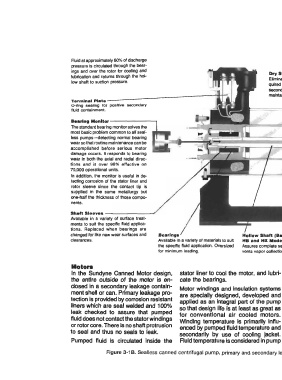
Figure 3-1 B. Sealless canned centrifugal pump, primary and secondary leakage containment. See Table 3-2. (Courtesy Sundstrand Fluid Handling Co.)