
Page 194 - APPLIED PROCESS DESIGN FOR CHEMICAL AND PETROCHEMICAL PLANTS, Volume 1, 3rd Edition
P. 194
Pumping of Liquids 165
Table 3-2 and plastic. The lined impellers are of the open or semi-
Approximate Capacity-Head Ranges For open type.
Centrifugal Pumps
=-- - ----=---··===-- - ����--=::.._ ::-----.c_ - ===---==---
Max. Casing
Max. Head*
Type GPM* Ft. Figure No. The casing may be constructed of a wide variety of met-
--------------------------
Single Stage (H) 600 225 3-1 and 3-2 als, as well as being lined to correspond to the material of
Canned, Sealless 2000 650 3-lA the impeller. Operating pressures go to about 5000 psi for
Canned, Sealless !000 800 3-IB the forged or cast steel barrel-type designs. However, the
Single Stage (V) >L:jO 250+ 3-3 usual process application is in the 75 psi to 1,000 psi
Double Suction, range, the latter being in light hydrocarbon and similar
Single Stage (H) 15,000 300 34 and 3-5 high vapor pressure systems.
Multistage (H) 3,000 5,000 3-6, -7, and -8
Single and Multistage (V) The removal of the casing parts is necessary for access
a. Mixed Flow CV) 100,000 75 3-11 Lo the impeller and often to the packing or seals. Some
b. Axial Flow (V) 100,000 25 3-10 designs are conveniently arranged to allow dismantling
c. Centrifugal (V) 400± 5,750 3-9, -12, -13 and -14 the casing without removing the piping connections.
There are proposed construction standards being consid-
''Not necessarily at same point.
(I-I) = Horizontal. ered which will allow easy maintenance of many of the
(V) = Vertical. t>ves now being offered in a non-standard fashion.
STATIONARY
FACE
SEAT
GASKET
-
GLAND
ROTATING
FACE���--�----�.-.:��'7':t
GASKET COIL ·-
SPRI �
SHAFT_.--
SLEEVE
DOUBLE
MECHANICAL
SEAL.
IMPELLER
SCREW
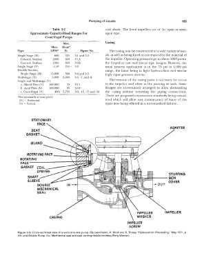
Figure 3-3. Cross-sectional view of a vertical in-line pump. (By permission, H. Knoll and S. Tinney, "Hydrocarbon Processing," May 1971, p.
131 and Goulds Pump, Inc. Mechanical seal and seal venting details courtesy Borg-Warner.)