
Page 214 - APPLIED PROCESS DESIGN FOR CHEMICAL AND PETROCHEMICAL PLANTS, Volume 1, 3rd Edition
P. 214
184 Applied Process Design for Chemical and Petrochemical Plants
-c:,
..
Atmospheric "" ...
Pressure ::c: Exit Loss
� I ;::
I
""
Suction Di.scharge iii D
..
I
Liquid Head Head ... Suction: h5 =S-hsL
�
hSL =Pipe, Fittings and
..
I s:; of her Friction Losses
Entrance I O_ i s_c_h_ a r..,_g_ e _..., u
Loss I Piping Cl Discharge: hd =D+hdL
I hdL =Pipe, Fittings and
Suction -·-·- other Friction Losses
Centerline
Piping Pump Note: Sw = Worst condition to
Pump
empty this tank, ft
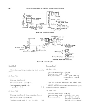
Figure 3-38. Suction head system.
Exit Loss
0
1
"" ..
� .. �,M
-c:,
-::c:
o:;:
i,;;.� s s=u
a;;
�·.;:
U) *Suction: h. = -SL - hsL
hsL = Pipe, Fitting, Valves,
Exchanger and
other Friction
Losses
-hs = SL+ hsL
**Discharge: hd = D + hdL
hdL = Pipe, Fittings and
other Friction
Losses
*Suction: Worst Case = S' L (Substitute in
above)
**Discharge: (Worst Case) use (D + D1
Figure 3-39. Suction lift system
Static Head Pressure Head
For Figure 3-40C
This is the overall height to which the liquid must be
raised.
Discharge pressure head = 100 psig
Suction pressure head = 0 psig
For Figure 3-40A Total pressure head = 100 - ( +O) = 100 psig
= 100(2.31)* = 231 ft of
water
Discharge static head: H
Suction static head: L (actually - L) Note: The totals are differentials and neither gauge
nor absolute values.
Total system static head: H + L; *Applies to water only. For the other fluids use appro-
actually H -- (- L) (3-4) priate specific gravity conversion.
For Figure 3-40D
For Figure 3-40B
Discharge pressure head= 100 psig
Discharge static head: I-I (from centerline of pump) Suction pressure head = + 50 psig ( =64. 7 psia)
Total pressure head = 100 - ( +50) = 50 psi
Suction static head: S, (actually +S)
not gauge or absolute =
Total system static head: 1-1 - S; or H- ( +S) (3-5) 50 (2.31) = 115.Sftofwater