
Page 216 - APPLIED PROCESS DESIGN FOR CHEMICAL AND PETROCHEMICAL PLANTS, Volume 1, 3rd Edition
P. 216
186 Applied Process Design for Chemical and Petrochemical Plants
es are a function of the characteristics of the fluid flowing
in the piping systems and the velocities of flow. Entrance
and exit losses relate to the pipe and not the suction or
discharge connections at the pump. Usually they are very s
small, but cannot be ignored without checking. Velocity
heads at the pump connections are considered internal
losses. These are handled by the manufacturer's design of Pump
the pump and are not considered with the external losses
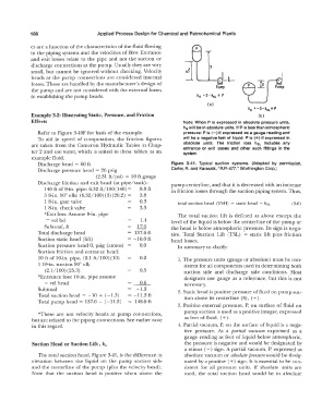
in establishing the pump heads. h5 = S- hSL + p
(al
h5 �-s-hSL+P
Example 3-2: Illustrating Static, Pressure, and Friction (bl
Effects Note: When P is expressed In absolute pressure units,
hs will be in absolute units. If P Is less than atmospheric
Refer to Figure 3-40F for basis of the example. pressure: Pis(-) If expressed as a gauge reading and
To aid in speed of computation, the friction figures will be a negative feet of liquid. P Is(+) If expressed In
absolute units. The friction loss hsL Includes any
are taken from the Cameron Hydraulic Tables in Chap- entrance or exit losses and other such fittings in the
ter 2 and use water, which is suited to these tables, as an system.
example fluid.
Discharge head = 60 ft Figure 3-41. Typical suction systems. (Adapted by permission,
Discharge pressure head = 26 psig Carter, A. and Karassik, "A.P.-477." Worthington Corp.)
(2.31 ft/psi) = 60 ft gauge
Discharge friction and exit head (at pipe/tank): pump centerline, and that it is decreased with an increase
140 ft of 8-in. pipe: 6.32 ft/100(140) = 8.8 ft in friction losses through the suction piping system. Thus,
3 8-in. goo ells: (6.32/100)(3)(20.2) 3.8
1 8-iu. gate valve 0.3 total suction head (TSH) = static head - hsL (3-6)
1 8-in. check valve 3.3
*Exit loss: Assume 8-in. pipe The total suction lift is defined as above except the
= vel hd 1.4 level of the liquid is below the centerline of the pump or
Subtotal, ft 17.6 the head is below atmospheric pressure. Its sign is nega-
Total discharge head 137.6 ft tive. Total Suction Lift (TSL) = static lift plus friction
Suction static head (lift) = -10.0 ft head losses.
Suction pressure head 0, psig (atmos) 0.0 In summary to clarify:
Suction friction and entrance head:
10 ft of 10-in. pipe, (2.1 ft/100) (10) 0.2 1. The pressure units (gauge or absolute) must be con-
1 l 0-in. suction go 0 ell; sistent for all components used in determining both
(2.l/100) (25.3) 0.5 suction side and discharge side conditions. Most
*En trance loss: l 0-in. pipe assume designers use gauge as a reference, but this is not
= vel head 0.6 necessary.
Subtotal -1.3 2. Static head is positive pressure of fluid on pump suc-
Total suction head = - 10 + (-1.3) = -11.3 ft tion above its centerline (S), ( +).
Total pump head r= 137.6 - (-11.3) = 148.9ft
3. Positive external pressure, P, on surface of fluid on
*These are not velocity heads at pump connections, pump suction is used as a positive integer, expressed
but are related to the piping connections. See earlier note as feet of fluid, ( +).
in this regard. 4. Partial vacuum, P, on the surface of liquid is a nega-
tive pressure. As a partial vacuum expressed as a
gauge reading as feet of liquid below atmospheric,
Suction Head or Suction Lift , h, the pressure is negative and would be designated by
a minus (-) sign. A partial vacuum, P, expressed as
The total suction head, Figure 3-41, is the difference in absolute vacuum or absolute pressure would be desig-
elevation between the liquid on the pump suction side nated by a positive ( +) sign. It is essential to be con-
and the centerline of the pump (plus the velocity head). sistent for all pressure units. If absolute units are
Note that the suction head is positive when above the used, the total suction head would be in absolute