
Page 219 - APPLIED PROCESS DESIGN FOR CHEMICAL AND PETROCHEMICAL PLANTS, Volume 1, 3rd Edition
P. 219
Pumping of Liquids 189
Cavitation of a centrifugal pump, or any pump, devel- worst possible operating conditions (see pump
ops when there is insufficient NPSH for the liquid lo flow curves Figures 3-36A, B, C) with pump curve values
into the inlet of the pump, allowing flashing or bubble for NPSH expressed as feet of liquid handled. These are
formation in the suction system and entrance to the the pump's required minimum NPSHR. The pump's
pump. Each pump design or "family" of dimensional fea- piping and physical external system provides the
tures related to the inlet and impeller eye area and available NPSHA.
entrance pattern requires a specific minimum value of
NPSH to operate satisfactorily without flashing, cavitating, NPSHA must be > NPSHR (3-8)
and loss of suction flow.
Under cavitating conditions a pump will perform 2. Internal clearance wear inside pump.
below its head-performance curve at any particular flow 3. Plugs in suction piping sysLem (screens, nozzles,
rate. Although the pump may operate under cavitation etc.).
conditions, it will often be noisy because of collapsing 4. Entrained gas (non-condensable).
vapor bubbles and severe pitting, and erosion of the 5. Deviations or fluctuations in suction side pressures,
impeller often results. This damage can become so severe temperatures (increases), low liquid level.
as to completely destroy the impeller and create excessive 6. Piping layout on suction, particularly tee-intersec-
clearances in the casing. To avoid these problems, the fol- tions, globe valves, baffles, long lines with numerous
lowing are a few situations to watch: elbows.
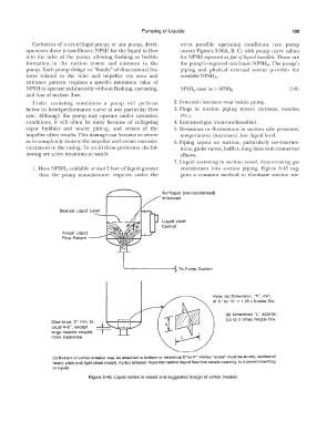
7. Liquid vortexing in suction vessel, thus creating gas
1. Have NPSHA available at least 2 feet of liquid greater entrainment into suction piping. Figure 3-43 sug-
than the pump manufacturer requires under the gests a common method to eliminate suction var-
Air/Vapor (non-condensed)
entrained
Desired Liquid Level
Liquid Level
Control
Actual Liquid
Flow Pattern �-�•'t-__.���,--J
---------- To Pump Suction
Note: (a) Dimension, "h", min.
of 5" to "h" = 1.25 x Nozzle Dia.
(b) Dimension "L" approx.
3.5 to 5 times Nozzle Dia.
Clearance, 2" min. to
usual 4-6", except
large nozzies require
more clearance.
(c) Bottom of vortex breaker may be attached to bottom or raised up 2" to 4". Vortex "cross" must be sturdy, welded of
heavy plate (not light sheet metal). Vortex breaker must not restrict liquid flow into nozzle opening, but prevent swirling
of liquid.
Figure 3-43. Liquid vortex in vessel and suggested design of vortex breaker.