
Page 295 - APPLIED PROCESS DESIGN FOR CHEMICAL AND PETROCHEMICAL PLANTS, Volume 1, 3rd Edition
P. 295
Mechanical Separations 265
c 1
�---;_-L- ,c;...._,.;,...;.._--=-_,_-_...,.,f
c
·e
-N Outlet Dip Pipe
� CD
a
s @) Tangential to
a shell wall
�
Inlet
•4-·-
(Also Dtsigned lo Wrap
"'t-"T"T.,-:r�-t
c
·e 90° lo 180° Araund Vt11tl
� 0
-N lo glH Tangential Inlet).
0
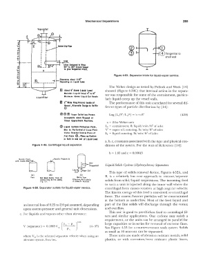
.., Figure 4-51. Separator inlets for liquid-vapor service .
a
:::,.
a � Clearance about 1112"
-I
s -- -- , ----- Depending on Liqaid Load
[i]
1 The Webre design as tested by Pollock and Work [14]
ffi About 6" AboH Liquid Ltwel showed (Figure 4-50C) that internal action in the separa-
Maintain Liquid Lent 4" to 12" tor was responsible for some of the entrainment, particu-
Liquid�Ou! Mini111u111 AboH Liquid Out Nozzle
larly liquid creep up the vessel walls.
IZI 2" Wide Ring Around l11id1 af The performance of this unit correlated for several dif-
V1111I , Alternate Dtsign to Baffle ferent types of particle distribution by [14]:
©
© @® Vapor Outlet hos Pronn ( 4-58)
Acceptable whn Stopped at
Thu Appro1i111ate Positions.
a = 2 for Webre unit
2
@ Liquid Surface Protection Plott, L,. = entrainment, lb liquid/min/ft of inlet
2
1101 b1 Perforated.If Cron-Plate V' = vapor vel. entering, lb/min/ft of inlet
Vortu Brtoktr Uud in Platt of L 1 = liquid entering, lb/min/ft of inlet
2
Flot Plall @, Place 10 Portion
i1 Both in ond out of Liquid Ln1I.
a, b, c, constants associated with the type and physical con-
Figure 4-49. Centrifugal liquid separator. ditions of the system. For the unit of Reference [14]:
b = 1.85 and c = 0.00643
""" '"'"' '"'LJ - Liquid-Solids Cyclone (Hydrocyclones) Separators
Nonie Flush
Inlet
(Tonqenliall
Li ��� t t Vapor Ou!
This type of solids removal device, Figures 4-52A, and
(Al IB) IC)
Poor Nol Much Betltr lhon IA) Webre T1pe B, is a relatively low cost approach to remove/separate
Unlen Ring Baffle Added, Effectivt • Particularf y solids from solid/liquid suspensions. The incoming feed
Fig.· 27. in Vacuum Service
to such a unit is injected along the inner wall where the
Figure 4-50. Separator outlets for liquid-vapor service. centrifugal force causes rotation at high angular velocity.
The kinetic energy of this feed is converted to centrifugal
force. The coarse/heavier particles will be concentrated
at the bottom as underflow. Most of the feed liquid and
an internal loss of0.25 to 2.0 psi assumed, depending part of the fine solids will discharge through the vortex
upon system pressure and general unit dimensions. and overflow.
e. For liquids and vapors other than air-water: This unit is good lo pre-thicken feed to centrifugal fil-
ters and similar applications. One cyclone may satisfy a
requirement, or the units can be arranged in parallel for
[ PL - P,. )0.25 large capacities or in series for removal of extreme fines.
V (separator) = 0.1885 V sn - ( 4- 57)
--p- " See Figure 4-53 for a counter-current wash system. Solids
as small as 10 microns can be separated.
where V,a is the selected separator velocity when using an These units are made of abrasion resistant metals, solid
air-water system, feet/sec. plastics, or with corrosion/wear resistant plastic liners,