Page 291 - APPLIED PROCESS DESIGN FOR CHEMICAL AND PETROCHEMICAL PLANTS, Volume 1, 3rd Edition
P. 291

Mechanical Separations                                    261

          c.  Select cylindrical  shell diameter,  D with  two consid-   Efficiency
                                          0
            erations in mind:
                                                                Typical estimating efficiencies are given in Figures 4-46
          • Large diameter reduces pressure drop             and 4-47.  Note the curves indicate how much dust of each
          • Small  diameter  has  higher  collection  efficiency  for   particle size will be collected.  The efficiency  increases  as
            the same entrance conditions and pressure drop.   the  pressure  drop  increases;  that  is,  a  smaller  separator
                                                             might  have  a  higher  efficiency  due  to  the  higher  gas
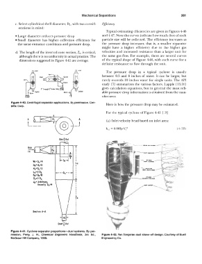
          d. The length of the inverted cone section, Zc,  is critical,   velocities  and  increased  resistance  than  a  larger unit for
            although there is no uniformity in actual practice. The   the same gas  flow.  For example,  there are  several  curves
            dimensions suggested in Figure 4-41  are average.   of the  typical  shape  of Figure  4-46,  with each  curve  for a
                                                             definite resistance to flow  through  the unit.

                      lnltl                    lnltl            The  pressure  drop  in  a  typical  cyclone  is  usually
                                             i               rarely  exceeds  10  inches  water for single  units.  The API
                        \nit!                                between  0.5  and  8  inches  of water.  It can  be  larger,  but
                                                             study  [7]  summarizes  the various factors.  Lapp  le  [ 13, 16]
                                                             gives  calculation  equations,  but in  general  the most reli-
                                               Oulltl        able pressure drop information is obtained from the man-
                                                             ufacturer.
        Figure 4-40. Centrifugal separator applications.  By permission, Cen-   Here is how the pressure drop may  be estimated.
        trlflx Corp.

                                                                For the typical cyclone of Figure 4-41  [13]
                 A                              A               (a)  Inlet velocity  head  based on inlet area:
                  L  _                       _j
                                                                hui  =  0.003p v(  2                      (4-53)


                  -                    I  I
                  Gas
                  In
                                       I
                                     __ .J. __ ..L
                                          Sc   I
                                    �-D,-..JT   I  I                                 -..   aT-l'AH
                     W1= Dc/4                 Le                                      DUIT  CHAHNll
                     D,• Dc/2                 I
                     He= Dc/2                 I  I                                  ---- IHIIT  ro•
                                                                                     oun lADIN  GASU
                     Lc•2 De       ---De--    I
                     Sc• Dc/8                 I  I
                     Zc•2 De      1-------J-t
                     Jc• Arbitrary,           I
                       Usually  Dc/4          I
                                              I
                                              I
                                              I
                                              I
                                              I
                                              fc
                                              I
                                              I
                                              I
                                              I
                                              I
                     Section A-A              I  I
                                         --1..
                                      Jc
                                   Dust J  Out
        Figure 4-41. Cyclone separator proportions-dust systems.  By per-
        mission,  Perry,  J.  H.,  Chemical  Engineers  Handbook,  3rd  Ed.,   Figure 4-42. Van Tongeran dust shave-off design.  Courtesy of Buell
        McGraw-Hill Company,  1950.                          Engineering Co.
   286   287   288   289   290   291   292   293   294   295   296