
Page 89 - APPLIED PROCESS DESIGN FOR CHEMICAL AND PETROCHEMICAL PLANTS, Volume 1, 3rd Edition
P. 89
Fluid Flow 73
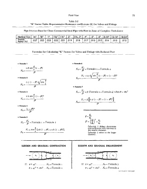
Table 2-2
"K" Factor Table: Representative Resistance coefficients (K) for Valves and Fittings
Pipe Friction Data for Clean Commercial Steel Pipe with Flow in Zone of Complete Turbulence
I Nominal Size w· �" 1" lW' 1 Y2" 2" 2%, 3" 4" S" 6" 8-1 O" I 1 2- 16" 18-24"
I Friction .027 .025 .023 .022 .021 .019 .Q18 .017 .016 .Q1 s .OU I I .ot 3 .012
Factor (fr)
Formulas for Calculating "K" Factors for Valves and Fittings with Reduced Port
• formula I • Formula 6
o.8 sin_!_(, - {J') K2 -1;: + Formula 2 + Formula 4
K,- 2
134 vsin
K1 + 0.5 ! (1 - {J'l) + (1 - {Jl)t
K, - 2
134
• formula 7
K
1
• formulci 3 K2 - 134 + fJ (Formula 2 + Formula 4) when e·- 18o 0
2.6 sin-!. ( 1 - {J'l) 2
Kt- - 2---
134
• Formula 4
� 1
K2 � + Formula r + Formula J
Subscript I defines dimensions
and coefficients with reference to
the smaller diameter.
Subscript 2 refers to the larger
diameter.
SUDDEN AND GRADUAL CONTRACTION SUDDEN AND GRADUAL ENLARGEMENT
,' � c '\ t I ,, '\ ' t .: ( I
9
i a, 1d, ' d, I I 81 ' I .--..... I 81 J d, ' d, I I 8, I
_,, ,/' 1 \ ::.i t ' 5 I ' / t t i ' ,/
If: 9 <: 45° K2 - Formula \ If: 9 <: 45° Kt - Formula J
9 > 45° <: 180° � - Formula 2 9 > 45° <: 180° Kt - Formula 4
( continued on next page)