
Page 94 - APPLIED PROCESS DESIGN FOR CHEMICAL AND PETROCHEMICAL PLANTS, Volume 1, 3rd Edition
P. 94
78 Applied Process Design for Chemical and Petrochemical Plants
o.er-- ........ -..,......-------------, Reynolds number and the friction factor for all conditions
of Ilow using the appropriate f and K values.
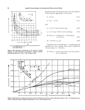
h=KxV'
2g
K = f (L/D) (2-25)
(2-31)
1 and:
2
hr= (fL/D) (v /2g), ft fluid for pipe (2-26)
2
hr = (K) (v /2g), ft fluid for valves and fittings (2-27)
AP/100 eq. ft*= 0.0668 (µv/d 2) = 0.0273 µQ/d4,
psi/ 100 eq. ft (2-32)
o.o�_.__.._____._......__.__�--__.---
0 5 10 AP= (AP/100) (Leq), psi (2-33)
o----
R
D *Equivalent feet of straight pipe; i.e., straight pipe plus
Note: 1.) Use 0.00085 ft for EID for uncoated cast iron and cast steel elbows.
2.) Not reliable when RID < 1.0. equivalents for valves, fittings, other system components
3.) R = radius of elbow, ft ( except vessels, etc.). Therefore,
Figure 2-13A. Resistance Coefficients for 90° bends of uniform
diameter for water. Reprinted by permission, Hydraulic Institute, AP/100 eq. ft= pressure drop (friction) per 100 equivalent
Engineering Data Book, 1st Ed., 1979, Cleveland, Ohio. feet of straight pipe
,
0.25
h=KxV 2
2g RID= 1
0.20---
K 0.151------1
7.5 15 22.5 30 37.5 45 52.5 60 67.5 75 82.5 90
���������������CX:o�����������.,.
Figure 2-138. Resistance coefficients for bends of uniform diameter and smooth surface at Reynolds number= 2.25 x 10 5. Reprinted by per-
mission, Hydraulic Institute, Engineering Data Book, 1st Ed., 1979, Cleveland, Ohio.