
Page 93 - APPLIED PROCESS DESIGN FOR CHEMICAL AND PETROCHEMICAL PLANTS, Volume 1, 3rd Edition
P. 93
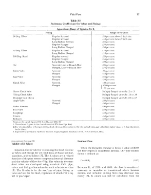
Fluid  Flow                                           77

                                                           Table 2-3
                                          Resistance Coefficients for Valves and Fittings
            ==� - -==-------- - ----
                                               Approximate Range of Variation for K
                       ----------
                                      Fitting                                             Range of Variation
           ----  -----------------�--------------------+----------�
            90 Deg.  Elbow                  Regular Screwed                         ±20 per cent above 2  inch size
                                            Regular Screwed                         ±40 per cent below 2  inch size
                                            Long Radius,  Screwed                   ±25 per cent
                                            Regular Flanged                         ±35  per cent
                                            Long Radius,  Flanged                   ±30 per cent
            45  Deg.  Elbow                 Regular Screwed                         ±10 per cent
                                            Long Radius,  Flanged                   ±10 per cent
            180 Deg.  Bend                  Regular screwed                         ±25 per cent
                                            Regular Flanged                         ±35  per cent
                                            Long Radius, Flanged                    ±30 per cent
            Tee                             Screwed, Line or Branch Flow            ±25  per cent
                                            Flanged, Line or Branch Flow            ±35 per cent
            Globe Valve                     Screwed                                 ±25 per cent
                                            Flanged                                 ±25 per cent
            Gate Valve                      Screwed                                 ±25 per cent
                                            Flanged                                 ±50 per cent
            Check Valve                     Screwed                                 ±30 per cent
                                            Flanged                                {  + 200 per cent
                                                                                    -80  per cent
            Sleeve Check Valve                                                      Multiply flanged values by .2 to .5
            Tilting Check Valve                                                     Multiply flanged values by .13  LO  .19
            Drainage Gate Check                                                     Multiply flanged values by _03 to .07
            Angle Valve                     Screwed                                 ±20  per cent
                                            Flanged                                 ±50  per cent
            Basket Strainer                                                         ±50  per cent
            Foot Valve                                                              ±50 per cent
            Couplings                                                               ±50 per cent
            Unions                                                                  ±50 per cent
            Reducers              �=�c===e''e="'e'--�=e---====-============��=-==±-50 per cent   _
            Notes on the use of Figlires 2-12 A.  and B,  and Table�--   -----
            1. The value of D  given  in the char  ls is  nominal !PS  (Iron  Pipe Size).
            2.  For velocities below  15 feet per second, check valves and foot valves will be only partially open and will exhibit higher values of K than that shown
             in  the charts,
            3_  Reprinted by permission Hydraulic Institute,  Engineering Data Handbook,  I st Ed.,  1979, Cleveland, Ohio.


           (text continued from page  72j                       Laminar Flow
          Validity of K Values
                                                                   'When  the  Reynolds  number is  below  a  value  of 2000,
             Equation 2-25 is valid for calculating the head loss clue   the  flow  region is  considered  laminar.  The  pipe  friction
           to valves  and fittings  for all  conditions  of flows:  laminar,   factor is defined as:
           transition,  and  turbulent  [3]. The K values  are  a  related
           function of the pipe system  component internal diameter
           and the velocity of flow for v /2g.  The values in the stan-   f =  64/R,,                         (2-17)
                                    2
           dard  tables  are  developed  using  standard  Al'\/SI  pipe,
           valves,  and fittings  dimensions for each schedule or class   Between  Re  of  2000  and  4000,  the  flow  is  considered
           [3].  The  K value  is  for  the  sizez'type  of pipe,  fitting,  or   unsteady  or  unstable  or  transitional  where  laminar
           valve and not for the fluid, regardless  of whether it is liq-   motion  and  turbulent  mixing  flows  may  alternate  ran-
           uid or gas/vapor.                                    domly  [3].  K  values  can  still  be  calculated  from  the